Toyota Yaris: Front Radar Sensor System / Terminals Of Ecu
TERMINALS OF ECU
NOTICE:
- Turning the ignition switch to ON with connectors disconnected may cause DTCs to be stored. Make sure to clear the DTCs after inspection has been performed.
- Do not apply excessive force to the millimeter wave radar sensor assembly connector.

CHECK MILLIMETER WAVE RADAR SENSOR ASSEMBLY
(a) Measure the voltage and resistance according to the value(s) in the table below.
| Terminal No. (Symbol) | Terminal Description | Condition | Specified Condition |
|---|---|---|---|
| B8-8 (IGB) - B8-1 (SGND) | Power source | Ignition switch ON | 10.5 to 16 V |
| Ignition switch off | Below 1 V | ||
| B8-1 (SGND) - Body ground | Ground | Always | Below 1 Ω |
 Problem Symptoms Table
PROBLEM SYMPTOMS TABLE HINT:
Use the table below to help determine the cause of problem symptoms. If multiple suspected areas are listed, the potential causes of the symptoms are listed in order of probability in the "Suspected Area" column of the table...
 Diagnosis System
DIAGNOSIS SYSTEM DIAGNOSIS FUNCTION (a) If a malfunction is detected in the millimeter wave radar sensor assembly, the millimeter wave radar sensor assembly stores DTCs without directly informing the driver, and sends malfunction signals to the systems that use the millimeter wave radar sensor assembly...
Other information:
Toyota Yaris XP210 (2020-2025) Reapir and Service Manual: Reassembly
REASSEMBLY PROCEDURE 1. INSTALL BACK DOOR DUST PROOF SEAL (a) Engage the claw to install 3 new back door dust proof seals. 2. INSTALL NO. 2 BACK DOOR WIRE (a) Engage the clamps to install the No. 2 back door wire. (b) Connect the 3 connectors...
Toyota Yaris XP210 (2020-2025) Reapir and Service Manual: Components
COMPONENTS ILLUSTRATION *1 NO. 1 VALVE ROCKER ARM SUB-ASSEMBLY *2 VALVE LASH ADJUSTER ASSEMBLY *3 VALVE STEM CAP *4 CYLINDER HEAD SUB-ASSEMBLY *5 CYLINDER HEAD GASKET *6 CYLINDER HEAD SET BOLT *7 NO. 1 CAMSHAFT BEARING CAP - - Tightening torque for "Major areas involving basic vehicle performance such as moving/turning/stopping" : N*m (kgf*cm, ft...
Categories
- Manuals Home
- Toyota Yaris Owners Manual
- Toyota Yaris Service Manual
- Fuse Panel Description
- Adjustment
- Power Integration No.1 System Missing Message (B235287,B235587,B235787-B235987)
- New on site
- Most important about car
Keys

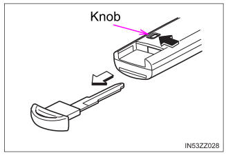
To use the auxiliary key, press the knob and pull out the auxiliary key from the smart key.

Copyright © 2025 www.toyaris4.com
