Toyota Yaris: Power Steering System / On-vehicle Inspection
ON-VEHICLE INSPECTION
PROCEDURE
1. CHECK STEERING EFFORT (TORQUE)
NOTICE:
These service operations may affect the SRS airbags. Be sure to read the precautionary notices concerning the SRS airbag system before servicing.
Click here

(a) Stop the vehicle on a level, paved surface and align the wheels straight ahead.
(b) Remove the horn button assembly.
Click here

(c) Connect the cable to the negative (-) auxiliary battery terminal.
Click here

(d) Using a torque wrench, check that the steering wheel set bolt is properly tightened.
Torque:
62 N·m {632 kgf·cm, 46 ft·lbf}
(e) Turn the power switch on (READY) so that the power steering is ready to operate. (for HV Model)
(f) Start the engine so that the power steering is ready to operate. (for Gasoline Model)
(g) Turn the steering wheel 90 degrees to the right and check steering effort (torque) with the steering wheel turned. Check in the opposite direction using the same method.
Standard Steering Effort (Reference):
5.5 N*m (56 kgf*cm, 49 in.*lbf) or less
(h) Align the front wheels facing straight ahead.
(i) Turn the ignition switch off.
(j) Disconnect the cable from the negative (-) auxiliary battery terminal.
Click here

(k) Install the horn button assembly.
Click here

 Diagnostic Trouble Code Chart
DIAGNOSTIC TROUBLE CODE CHART Power Steering System DTC No. Detection Item DTC Detection Condition Warning Indicate Return-to-normal Condition Note Link C05D604 Power Steering Control Module Processor System Internal Failure ECU internal malfunction (CPU malfunction) EPS warning light: Comes on Ignition switch ON again -
C05D646 Power Steering Control Module Processor Calibration / Parameter Memory Failure ECU internal malfunction (EEPROM error) EPS warning light: Comes on Ignition switch ON again -
C05D649 Power Steering Control Module Processor Internal Electronic Failure ECU internal malfunction (Peripheral circuit malfunction) EPS warning light: Comes on Ignition switch ON again -
C10001C Control Module Internal Temperature Sensor "A" Circuit Voltage Out of Range ECU temperature sensor "A" range malfunction EPS warning light: Comes on The ECU judges the system has returned to normal -
C123A17 Supply Voltage Circuit Circuit Voltage Above Threshold IG voltage is 18...
 Vehicle Control History
VEHICLE CONTROL HISTORY DESCRIPTION
Vehicle Control History is a function that captures and stores ECU data when triggered by specific vehicle behavior...
Other information:
Toyota Yaris XP210 (2020-2026) Reapir and Service Manual: IG Circuit Short to Ground (B227111)
DESCRIPTION This DTC is stored when a malfunction in the IG circuit or IG hold circuit of the certification ECU (smart key ECU assembly) is detected. DTC No. Detection Item DTC Detection Condition Trouble Area Note B227111 IG Circuit Short to Ground When either of the following conditions is met (1-trip detection logic*1): The IG circuit of the certification ECU (smart key ECU assembly) is malfunctioning...
Toyota Yaris XP210 (2020-2026) Reapir and Service Manual: Installation
INSTALLATION PROCEDURE 1. INSTALL FRONT BUMPER ASSEMBLY (a) Install the 3 grommets. HINT: Use the same procedure for the RH side and LH side. (b) Temporarily install the front bumper assembly with the 2 clips and 2 bolts. (c) w/ Pre-collision System: (1) Connect the connector...
Categories
- Manuals Home
- Toyota Yaris Owners Manual
- Toyota Yaris Service Manual
- Power Integration No.1 System Missing Message (B235287,B235587,B235787-B235987)
- Fuse Panel Description
- Opening and Closing the Liftgate/Trunk Lid
- New on site
- Most important about car
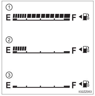
Fuel Gauge
The fuel gauge shows approximately how much fuel is remaining in the tank when the ignition is switched ON. We recommend keeping the tank over 1/4 full.