Toyota Yaris: Sfi System / Actuator Cut Circuit Stuck Off (P16B09F)
MONITOR DESCRIPTION
The ECM monitors the operation of the throttle actuator. When a malfunction is detected in the throttle actuator cut circuit immediately after the ignition switch is turned off, the ECM illuminates the MIL and stores a DTC.
| DTC No. | Detection Item | DTC Detection Condition | Trouble Area | MIL | Note |
|---|---|---|---|---|---|
| P16B09F | Actuator Cut Circuit Stuck Off | ECM main CPU malfunction (1 trip detection logic). |
| Comes on | SAE: P16B0 |
MONITOR STRATEGY
| Required Sensors/Components | ECM |
| Frequency of Operation | Once per driving cycle |
CONFIRMATION DRIVING PATTERN
- Connect the GTS to the DLC3.
- Turn the ignition switch to ON.
- Turn the GTS on.
- Clear the DTCs (even if no DTCs are stored, perform the clear DTC procedure).
- Turn the GTS off.
- Turn the ignition switch off.
- Disconnect the GTS.
- Disconnect the cable from the negative (-) auxiliary battery terminal and wait for 1 minute.
- Connect the cable to the negative (-) auxiliary battery terminal.
- Connect the GTS to the DLC3.
- Turn the ignition switch to ON.
- Turn the GTS on.
- Wait 1 second or more.
- Turn the ignition switch off and wait for at least 30 seconds.
- Turn the ignition switch to ON.
- Enter the following menus: Powertrain / Engine / Trouble Codes.
-
Read the pending DTCs.
HINT:
- If a pending DTC is output, the system is malfunctioning.
- If a pending DTC is not output, perform the following procedure.
- Enter the following menus: Powertrain / Engine / Utility / All Readiness.
- Input the DTC: P16B09F.
-
Check the DTC judgment result.
GTS Display
Description
NORMAL
- DTC judgment completed
- System normal
ABNORMAL
- DTC judgment completed
- System abnormal
INCOMPLETE
- DTC judgment not completed
- Perform driving pattern after confirming DTC enabling conditions
HINT:
- If the judgment result is NORMAL, the system is normal.
- If the judgment result is ABNORMAL, the system is malfunctioning.
CAUTION / NOTICE / HINT
NOTICE:
-
After the ignition switch is turned off, there may be a waiting time before disconnecting the negative (-) auxiliary battery terminal.
Click here

-
When disconnecting and reconnecting the auxiliary battery.
HINT:
When disconnecting and reconnecting the auxiliary battery, there is an automatic learning function that completes learning when the respective system is used.
HINT:
- Read Freeze Frame Data using the GTS. The ECM records vehicle and driving condition information as Freeze Frame Data the moment a DTC is stored. When troubleshooting, Freeze Frame Data can help determine if the vehicle was moving or stationary, if the engine was warmed up or not, if the air fuel ratio was lean or rich, and other data from the time the malfunction occurred.
PROCEDURE
| 1. | CLEAR DTC |
(a) Clear the DTCs.
Powertrain > Engine > Clear DTCs(b) Turn the ignition switch off and wait for at least 30 seconds.
|

| 2. | READ OUTPUT DTC (DTC P16B09F) |
(a) Disconnect the cable from the negative (-) auxiliary battery terminal and wait for 1 minute.
(b) Connect the cable to the negative (-) auxiliary battery terminal.
(c) Wait 1 second or more.
(d) Read the DTCs.
Powertrain > Engine > Trouble Codes| Result | Proceed to |
|---|---|
| DTCs are not output | A |
| P16B09F is output | B |
| A |
 | CHECK FOR INTERMITTENT PROBLEMS |
|

| 3. | REPLACE ECM |
Click here

|

| 4. | INSPECT THROTTLE BODY WITH MOTOR ASSEMBLY (THROTTLE VALVE) |
(a) Check if the throttle valve opens and closes smoothly.
OK:
Throttle valve opens and closes smoothly.
HINT:
-
When cleaning or replacing one throttle body with motor assembly, clean the other throttle body with motor assembly.
Click here

-
Perform "Inspection After Repair" after replacing the throttle body with motor assembly.
Click here

| OK |
 | END |
| NG |
 | REPLACE THROTTLE BODY WITH MOTOR ASSEMBLY |
 Air Intake Control Valve Circuit Short to Ground or Open (P166014)
DESCRIPTION The air cleaner is equipped with two inlets, one of which is opened or closed by the Air Intake Control Valve (AICV). This system reduces intake noise and increases engine power at low-to-high engine speed range...
 Throttle Actuator "A" Control Motor Circuit Current Below Threshold (P210018,P210019)
DESCRIPTION The throttle actuator is operated by the ECM and opens and closes the throttle valve using gears. The opening angle of the throttle valve is detected by the throttle position sensor, which is mounted on the throttle body with motor assembly...
Other information:
Toyota Yaris XP210 (2020-2025) Reapir and Service Manual: Precaution
PRECAUTION MAINTENANCE PRECAUTION (a) If the turbocharger sub-assembly is found to be defective, it must be replaced. Make sure to identify the cause of the problem including the conditions under which the turbocharger sub-assembly was used. Repair or replace the following as necessary: (1) Engine oil (level and quality) (2) Oil lines leading to the turbocharger sub-assembly (b) Be careful when removing and reinstalling the turbocharger sub-assembly...
Toyota Yaris XP210 (2020-2025) Reapir and Service Manual: Freeze Frame Data
FREEZE FRAME DATA FREEZE FRAME DATA (a) When a DTC is stored, the AWD ECU assembly stores the current vehicle state as Freeze Frame Data. HINT: Freeze Frame Data at the time a DTC is stored: When the AWD ECU assembly stores data at the time a DTC is stored, no updates will be performed until the data is cleared...
Categories
- Manuals Home
- Toyota Yaris Owners Manual
- Toyota Yaris Service Manual
- Key Battery Replacement
- To Set Speed
- Removal
- New on site
- Most important about car
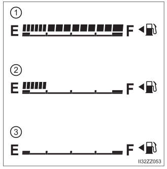
Fuel Gauge
The fuel gauge shows approximately how much fuel is remaining in the tank when the ignition is switched ON. We recommend keeping the tank over 1/4 full.