Toyota Yaris: Smart Key System (for Start Function) / System Diagram
SYSTEM DIAGRAM
SMART KEY SYSTEM (for Start Function)


SMART KEY SYSTEM (for Entry Function)
Click here

 Parts Location
PARTS LOCATION ILLUSTRATION
*1 ECM *2 NO. 1 ENGINE ROOM RELAY BLOCK ASSEMBLY - ST NO. 1 FUSE - EFI NO. 1 FUSE - IGP RELAY - ST NO. 1 RELAY *3 SKID CONTROL ECU (BRAKE ACTUATOR ASSEMBLY) - - ILLUSTRATION
*1 NO...
 How To Proceed With Troubleshooting
CAUTION / NOTICE / HINT HINT:
Replace parts related to the wireless door lock control system and smart key system according to the inspection procedure...
Other information:
Toyota Yaris XP210 (2020-2025) Reapir and Service Manual: Components
COMPONENTS ILLUSTRATION *1 COWL SIDE TRIM BOARD RH *2 FRONT DOOR SCUFF PLATE RH *3 FRONT DOOR OPENING TRIM WEATHERSTRIP RH *4 GLOVE COMPARTMENT DOOR ASSEMBLY *5 LOWER NO. 2 INSTRUMENT PANEL FINISH PANEL *6 CENTER LOWER INSTRUMENT COVER *7 LOWER INSTRUMENT PANEL FINISH PANEL *8 NO...
Toyota Yaris XP210 (2020-2025) Reapir and Service Manual: Check Mode Procedure
CHECK MODE PROCEDURE HINT: Compared to normal mode, check mode is more sensitive to malfunctions. Therefore, check mode can detect malfunctions that cannot be detected in normal mode. NOTICE: All the stored DTCs and freeze frame data are cleared if: 1) the engine stop and start ECU is switched from normal mode to check mode or vice versa; or 2) the ignition switch is turned from ON to ACC or off while in check mode...
Categories
- Manuals Home
- Toyota Yaris Owners Manual
- Toyota Yaris Service Manual
- Starting the Engine
- To Set Speed
- How to connect USB port/Auxiliary jack
- New on site
- Most important about car
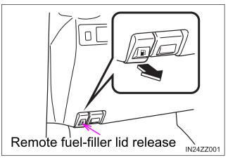
Refueling
Before refueling, close all the doors, windows, and the liftgate/trunk lid, and switch the ignition OFF.
To open the fuel-filler lid, pull the remote fuel-filler lid release.
Copyright © 2025 www.toyaris4.com