Toyota Yaris: Rear Speed Sensor / Removal
REMOVAL
CAUTION / NOTICE / HINT
HINT:
- Use the same procedure for the RH side and LH side.
- The following procedure is for the LH side.
- If the rear speed sensor rotor needs to be replaced, replace the rear axle hub and bearing assembly.
PROCEDURE
1. REMOVE REAR WHEEL
Click here

2. REMOVE QUARTER TRIM PANEL ASSEMBLY
Click here

3. SEPARATE NO. 3 PARKING BRAKE CABLE ASSEMBLY
| (a) Remove the nut to separate the No. 3 parking brake cable assembly. |
|

4. REMOVE REAR SPEED SENSOR
| (a) Disconnect the rear speed sensor connector inside of the vehicle. |
|

| (b) Remove the bolt and separate the rear speed sensor from the vehicle body. |
|
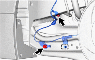
(c) Remove the bolt and separate the rear speed sensor from the rear trailing arm assembly.
(d) Disengage the clamp and separate the rear speed sensor from the rear trailing arm assembly.
| (e) Disengage the clamp and separate the rear speed sensor from the rear trailing arm assembly. |
|
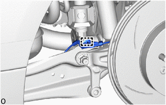
| (f) Remove the bolt to separate the rear speed sensor from the rear axle carrier sub-assembly. |
|
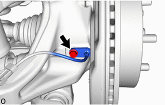
| (g) Disengage the grommet and remove the rear speed sensor. NOTICE:
|
|

 Components
COMPONENTS ILLUSTRATION
*1 REAR SPEED SENSOR *2 NO. 3 PARKING BRAKE CABLE ASSEMBLY
Tightening torque for "Major areas involving basic vehicle performance such as moving/turning/stopping" : N*m (kgf*cm, ft...
 Installation
INSTALLATION CAUTION / NOTICE / HINT HINT:
Use the same procedure for the RH side and LH side.
The following procedure is for the LH side.
If the rear speed sensor rotor needs to be replaced, replace the rear axle hub and bearing assembly...
Other information:
Toyota Yaris XP210 (2020-2025) Reapir and Service Manual: Main Body ECU Communication Stop Mode
DESCRIPTION Detection Item Symptom Trouble Area Main Body ECU Communication Stop Mode Communication stop for "Main Body" is indicated on the "Communication Bus Check" screen of the GTS. Click here Main body ECU (multiplex network body ECU) main line or connector Power source circuit of main body ECU (multiplex network body ECU) or power distribution box assembly Main body ECU (multiplex network body ECU) or power distribution box assembly ground circuit Main body ECU (multiplex network body ECU) or power distribution box assembly WIRING DIAGRAM CAUTION / NOTICE / HINT CAUTION: When performing the confirmation driving pattern, obey all speed limits and traffic laws...
Toyota Yaris XP210 (2020-2025) Reapir and Service Manual: Freeze Frame Data
FREEZE FRAME DATA DESCRIPTION The ECM records vehicle and driving condition information as Freeze Frame Data the moment a DTC is stored. When troubleshooting, Freeze Frame Data can be helpful in determining whether the vehicle was moving or stationary, whether the engine was warmed up or not, whether the air fuel ratio was lean or rich, as well as other data recorded at the time of a malfunction...
Categories
- Manuals Home
- Toyota Yaris Owners Manual
- Toyota Yaris Service Manual
- Opening and Closing the Liftgate/Trunk Lid
- How to use USB mode
- Speedometer, Odometer, Trip Meter and Trip Meter Selector
- New on site
- Most important about car
Turning the Engine Off
Stop the vehicle completely. Manual transaxle: Shift into neutral and set the parking brake.Automatic transaxle: Shift the selector lever to the P position and set the parking brake.
Press the push button start to turn off the engine. The ignition position is off.