Toyota Yaris: G16e-gts (engine Control) / Relay
Inspection
INSPECTION
PROCEDURE
1. INSPECT NO.1 ELECTRONIC FUEL INJECTION MAIN RELAY (EFI-MAIN NO. 1)
| (a) Measure the resistance according to the value(s) in the table below. Standard Resistance:
If the result is not as specified, replace the No.1 electronic fuel injection main relay (EFI-MAIN NO. 1). |
|

2. INSPECT NO.2 ELECTRONIC FUEL INJECTION MAIN RELAY (EFI-MAIN NO. 2)
| (a) Measure the resistance according to the value(s) in the table below. Standard Resistance:
If the result is not as specified, replace the No.2 electronic fuel injection main relay (EFI-MAIN NO. 2). |
|

3. INSPECT NO.3 ELECTRONIC FUEL INJECTION MAIN RELAY (EFI-MAIN NO. 3)
| (a) Measure the resistance according to the value(s) in the table below. Standard Resistance:
If the result is not as specified, replace the No.3 electronic fuel injection main relay (EFI-MAIN NO. 3). |
|

4. INSPECT IGP RELAY
| (a) Measure the resistance according to the value(s) in the table below. Standard Resistance:
If the result is not as specified, replace the igp relay. |
|

 Installation
INSTALLATION PROCEDURE 1. INSTALL MASS AIR FLOW METER (a) Install the mass air flow meter to the air cleaner cap sub-assembly with the 2 screws. NOTICE:
If the mass air flow meter has been struck or dropped, replace it...
 Sfi System
..
Other information:
Toyota Yaris XP210 (2020-2025) Reapir and Service Manual: Power Source Mode does not Change to ON (ACC)
DESCRIPTION If the engine switch is pressed with the electrical key transmitter sub-assembly in the cabin, the certification ECU (smart key ECU assembly) receives a signal and changes the power source mode. Related Data List and Active Test Items Problem Symptom Data List and Active Test Power source mode does not change to on (ACC) but does change to on (IG) Power Source Control Power Supply Condition ACC Relay Monitor WIRING DIAGRAM CAUTION / NOTICE / HINT NOTICE: When using the GTS with the ignition switch off, connect the GTS to the DLC3 and turn a courtesy light switch on and off at intervals of 1...
Toyota Yaris XP210 (2020-2025) Reapir and Service Manual: Components
COMPONENTS ILLUSTRATION *A for Front Passenger Side *B for Driver Side *1 FRONT DOOR LOWER FRAME BRACKET GARNISH *2 MULTIPLEX NETWORK MASTER SWITCH ASSEMBLY WITH FRONT ARMREST BASE UPPER PANEL *3 POWER WINDOW REGULATOR SWITCH ASSEMBLY WITH FRONT ARMREST BASE UPPER PANEL *4 FRONT DOOR TRIM GARNISH *5 FRONT DOOR TRIM BOARD SUB-ASSEMBLY *6 FRONT DOOR GLASS INNER WEATHERSTRIP *7 FRONT NO...
Categories
- Manuals Home
- Toyota Yaris Owners Manual
- Toyota Yaris Service Manual
- Brake System Control Module "A" System Voltage System Voltage Low (C137BA2)
- Key Battery Replacement
- To Set Speed
- New on site
- Most important about car
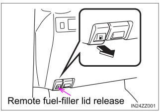
Refueling
Before refueling, close all the doors, windows, and the liftgate/trunk lid, and switch the ignition OFF.
To open the fuel-filler lid, pull the remote fuel-filler lid release.