Toyota Yaris: Lighting System / Rear Fog Light Circuit
DESCRIPTION
The main body ECU (multiplex network body ECU) controls the rear fog light.
WIRING DIAGRAM

CAUTION / NOTICE / HINT
NOTICE:
-
Before replacing the main body ECU (multiplex network body ECU), refer to Registration.
Click here
.gif)
-
First, confirm that there is no malfunction in the power integration system. Refer to the How to Proceed with Troubleshooting procedure.
Click here
-
First perform the communication function inspections in How to Proceed with Troubleshooting to confirm that there are no CAN communication malfunctions before troubleshooting this symptom.
Click here
-
First perform the communication function inspections in How to Proceed with Troubleshooting to confirm that there are no CXPI communication malfunctions before troubleshooting this symptom.
Click here
PROCEDURE
| 1. | READ VALUE USING GTS |
(a) Turn the light control switch to the TAIL position.
(b) Turn the rear fog light switch on.
(c) Using the GTS, read the Data List.
Body Electrical > Power Distribution Box > Data List| Tester Display | Measurement Item | Range | Normal Condition | Diagnostic Note |
|---|---|---|---|---|
| Rear Fog Light Fuse Shut Off Status | Rear fog light fuse condition | OFF or ON | OFF: Rear fog light fuse not shut off ON: Rear fog light fuse shut off | - |
| Tester Display |
|---|
| Rear Fog Light Fuse Shut Off Status |
OK:
The Data List value displays "OFF".
| NG |
.gif) | GO TO STEP 3 |
|
.gif)
| 2. | READ VALUE USING GTS |
(a) Using the GTS, read the Data List.
Body Electrical > Power Distribution Box > Data List| Tester Display | Measurement Item | Range | Normal Condition | Diagnostic Note |
|---|---|---|---|---|
| Rear Fog Light Output Signal | Rear fog light output | OFF or ON | OFF: Rear fog light is not output ON: Rear fog light is output | - |
| Tester Display |
|---|
| Rear Fog Light Output Signal |
OK:
Display changes according to the rear fog light switch operation.
| OK |
| REPLACE POWER DISTRIBUTION BOX ASSEMBLY |
| NG |
| REPLACE MAIN BODY ECU (MULTIPLEX NETWORK BODY ECU) |
| 3. | INSPECT REAR FOG LIGHT ASSEMBLY |
(a) Disconnect the W8 rear fog light LED connector.
(b) Turn the rear fog light switch off.
(c) Turn the rear fog light switch on.
(d) Using the GTS, read the Data List.
Body Electrical > Power Distribution Box > Data List| Tester Display | Measurement Item | Range | Normal Condition | Diagnostic Note |
|---|---|---|---|---|
| Rear Fog Light Fuse Shut Off Status | Rear fog light fuse condition | OFF or ON | OFF: Rear fog light fuse not shut off ON: Rear fog light fuse shut off | - |
OK:
The Data List value displays "OFF".
| OK |
| REPLACE REAR FOG LIGHT ASSEMBLY |
|
| 4. | CHECK HARNESS AND CONNECTOR |
(a) Disconnect the W8 rear fog light LED connector.
(b) Disconnect the cable from the negative (-) auxiliary battery terminal.
(c) Disconnect the 4E power distribution box assembly connector.
(d) Measure the resistance according to the value(s) in the table below.
Standard Resistance:
| Tester Connection | Condition | Specified Condition |
|---|---|---|
| W8-2 (B) or 4E-7 - Body ground | Always | 10 kΩ or higher |
| OK |
| REPLACE POWER DISTRIBUTION BOX ASSEMBLY |
| NG |
| REPAIR OR REPLACE HARNESS OR CONNECTOR |
 Front Fog Light Circuit
DESCRIPTION The main body ECU (multiplex network body ECU) controls the front fog lights. WIRING DIAGRAM
CAUTION / NOTICE / HINT NOTICE:
Before replacing the main body ECU (multiplex network body ECU), refer to Registration...
 Hazard Warning Switch Circuit
DESCRIPTION The combination meter assembly receives the hazard warning signal switch assembly on signal and controls the operation of the hazard warning lights...
Other information:
Toyota Yaris XP210 (2020-2025) Reapir and Service Manual: Installation
INSTALLATION PROCEDURE 1. INSTALL CLUTCH PEDAL PAD (a) Install the clutch pedal pad to the clutch pedal sub-assembly. 2. INSTALL NO. 1 PEDAL SPRING HOOK (a) Install the 2 No. 1 pedal spring hooks to the clutch pedal bracket sub-assembly. 3. INSTALL CLUTCH PEDAL SPRING HOLDER (a) Install the clutch pedal spring holder to the clutch pedal sub-assembly...
Toyota Yaris XP210 (2020-2025) Owner's Manual: Tiedown Hook-Rear
The hook positioned under the rear bumper on the right side is for tying down the vehicle during transport, and it cannot be used for towing other vehicles. It can be used as a towing hook only when the vehicle must be towed by another vehicle in an emergency case such as when the vehicle is stuck in snow, however, it may damage the bumper...
Categories
- Manuals Home
- Toyota Yaris Owners Manual
- Toyota Yaris Service Manual
- Speedometer, Odometer, Trip Meter and Trip Meter Selector
- Starting the Engine
- Fuse Panel Description
- New on site
- Most important about car
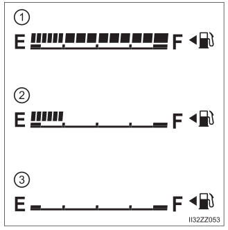
Fuel Gauge
The fuel gauge shows approximately how much fuel is remaining in the tank when the ignition is switched ON. We recommend keeping the tank over 1/4 full.