Toyota Yaris: Rear Crankshaft Oil Seal / Installation
INSTALLATION
CAUTION / NOTICE / HINT
NOTICE:
This procedure includes the installation of small-head bolts. Refer to Small-Head Bolts of Basic Repair Hint to identify the small-head bolts.
Click here

PROCEDURE
1. INSTALL REAR ENGINE OIL SEAL
(a) Using height adjustment attachments and plate lift attachments, place the engine assembly on a flat level surface.
NOTICE:
- Using height adjustment attachments and plate lift attachments, keep the engine assembly level.
- To prevent the oil pan sub-assembly from deforming, do not place any attachments under the oil pan sub-assembly of the engine assembly.
- Using an engine sling device and engine lift, secure the engine assembly before servicing.
(b) Apply MP grease to the lip of a new rear engine oil seal.
NOTICE:
- Keep the lip free from foreign matter.
- Do not allow MP grease to contact the dust seal.
| (c) Using SST and a hammer, tap in the rear engine oil seal. SST: 09223-15030 SST: 09950-70010 09951-07150 Standard Depth: -0.9 to 1.1 mm (-0.0354 to 0.0433 in.) (From the edge of the cylinder block sub-assembly and stiffening crankcase assembly) NOTICE: Do not tap in the rear engine oil seal at an angle. |
|

2. INSTALL NO. 1 CRANKSHAFT POSITION SENSOR PLATE
| (a) Install the No. 1 crankshaft position sensor plate. HINT: Align the pin hole of the No. 1 crankshaft position sensor plate with the pin of the crankshaft. |
|

3. INSTALL FLYWHEEL SUB-ASSEMBLY
| (a) Using SST, hold the crankshaft pulley assembly. SST: 09213-54015 SST: 09330-00021 |
|

(b) Clean the bolt holes.
| (c) Install and uniformly tighten the 8 bolts in several steps in the sequence shown in the illustration. Torque: 115 N·m {1173 kgf·cm, 85 ft·lbf} NOTICE: Do not start the engine for at least 1 hour after installing the drive plate and ring gear sub-assembly. |
|

4. INSTALL CLUTCH DISC ASSEMBLY
Click here

 Removal
REMOVAL CAUTION / NOTICE / HINT The necessary procedures (adjustment, calibration, initialization, or registration) that must be performed after parts are removed, installed, or replaced during the rear engine oil seal removal/installation are shown below...

Other information:
Toyota Yaris XP210 (2020-2025) Reapir and Service Manual: Brake Switch "B" Circuit Short to Battery (P070312)
DESCRIPTION The stop light switch assembly is part of a duplex system that transmits two signals: STP and ST1-. These two signals are used by the ECM to monitor whether or not the brake system is working properly. This DTC indicates that the stop light switch assembly remains on...
Toyota Yaris XP210 (2020-2025) Owner's Manual: Windshield Defrosting and Defogging
Set the mode selector dial to the position and turn the fan control dial to the desired speed. In this position, the outside air position is automatically selected, and when the fan control dial is ON, the air conditioner automatically turns on...
Categories
- Manuals Home
- Toyota Yaris Owners Manual
- Toyota Yaris Service Manual
- Key Battery Replacement
- To Set Speed
- Fuel Gauge
- New on site
- Most important about car
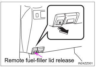
Refueling
Before refueling, close all the doors, windows, and the liftgate/trunk lid, and switch the ignition OFF.
To open the fuel-filler lid, pull the remote fuel-filler lid release.