Toyota Yaris: Fuel Sender Gauge Assembly / Inspection
INSPECTION
PROCEDURE
1. INSPECT FUEL SENDER GAUGE ASSEMBLY
CAUTION:
Perform the inspection in a well-ventilated area.
Do not perform the inspection near an open flame.
(a) Check that the float moves smoothly between F and E.
(b) Check the fuel sender gauge assembly voltage.
| (1) Apply 5 V between terminals 2 and 3. NOTICE:
HINT: If a stable power supply is not available, connect 4 nickel-metal hydride batteries (1.2 V each) or equivalent in series. |
|

| (2) Measure the voltage according to the value(s) in the table below. Standard Voltage:
*: The output voltage changes depending on the voltage applied to the terminals. Output voltage (F) = (0.851 x Voltage applied to terminals) to (0.921 x Voltage applied to terminals) Output voltage (E) = (0.069 x Voltage applied to terminals) to (0.139 x Voltage applied to terminals) If the result is not as specified, replace the fuel sender gauge assembly. |
|

2. INSPECT NO. 2 FUEL SENDER GAUGE ASSEMBLY
CAUTION:
Perform the inspection in a well-ventilated area.
Do not perform the inspection near an open flame.
(a) Check that the float moves smoothly between F and E.
(b) Check the No. 2 fuel sender gauge assembly voltage.
| (1) Apply 5 V between terminals 2 and 3. NOTICE:
HINT: If a stable power supply is not available, connect 4 nickel-metal hydride batteries (1.2 V each) or equivalent in series. |
|

| (2) Measure the voltage according to the value(s) in the table below. Standard Voltage:
*: The output voltage changes depending on the voltage applied to the terminals. Output voltage (F) = (0.851 x Voltage applied to terminals) to (0.921 x Voltage applied to terminals) Output voltage (E) = (0.069 x Voltage applied to terminals) to (0.139 x Voltage applied to terminals) If the result is not as specified, replace the No. 2 fuel sender gauge assembly. |
|

 Removal
REMOVAL CAUTION / NOTICE / HINT CAUTION:
Never perform work on fuel system components near any possible ignition sources.
Vaporized fuel could ignite, resulting in a serious accident...
 Installation
INSTALLATION PROCEDURE 1. INSTALL NO. 2 FUEL SENDER GAUGE ASSEMBLY (a) Attach the claw and install the No. 2 fuel sender gauge assembly. NOTICE: Be careful not to bend the arm of the fuel sender gauge assembly...
Other information:
Toyota Yaris XP210 (2020-2025) Reapir and Service Manual: Operation Check
OPERATION CHECK PRECAUTION FOR OPERATION CHECK Be sure to read Precaution thoroughly before servicing. Click here Be sure to correctly follow the removal and installation procedures for the SRS parts. NOTICE: If there is any damage or deformation of airbag installation components or the areas they are installed to, do not attempt to repair them...
Toyota Yaris XP210 (2020-2025) Reapir and Service Manual: Installation
INSTALLATION CAUTION / NOTICE / HINT PROCEDURE 1. INSTALL BLOWER ASSEMBLY (a) Engage the claws to install the blower assembly. (b) Install the 3 screws. (c) Connect the connector. 2. INSTALL AIR CONDITIONER UNIT ASSEMBLY Click here 3...
Categories
- Manuals Home
- Toyota Yaris Owners Manual
- Toyota Yaris Service Manual
- Key Battery Replacement
- Removal
- Engine & Hybrid System
- New on site
- Most important about car
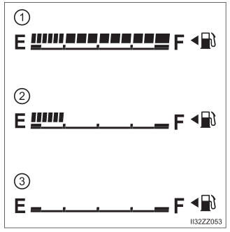
Fuel Gauge
The fuel gauge shows approximately how much fuel is remaining in the tank when the ignition is switched ON. We recommend keeping the tank over 1/4 full.