Toyota Yaris: Lighting System / IG Signal Circuit
DESCRIPTION
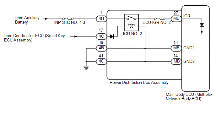
This circuit detects the ignition switch ON or off condition, and sends it to the main body ECU (multiplex network body ECU).
WIRING DIAGRAM
CAUTION / NOTICE / HINT
NOTICE:
- Inspect the fuses for circuits related to this system before performing the following procedure.
-
First, check for entry and start system (for Start Function) DTCs, and after confirming that there is no malfunction, proceed with troubleshooting.
Click here

-
Before replacing the main body ECU (multiplex network body ECU), refer to Registration.
Click here

PROCEDURE
| 1. | READ VALUE USING GTS |
(a) Read the Data List according to the display on the GTS.
Body Electrical > Main Body > Data List| Tester Display | Measurement Item | Range | Normal Condition | Diagnostic Note |
|---|---|---|---|---|
| IGR Power | Ignition switch ON signal | OFF or ON | OFF: Ignition switch off ON: Ignition switch ON | - |
| Tester Display |
|---|
| IGR Power |
OK:
Normal conditions listed above are displayed.
| OK |
 | PROCEED TO NEXT SUSPECTED AREA SHOWN IN PROBLEM SYMPTOMS TABLE |
|

| 2. | CHECK HARNESS AND CONNECTOR (POWER DISTRIBUTION BOX ASSEMBLY - POWER SOURCE) |
(a) Disconnect the 4C and 4H power distribution box assembly connectors.
(b) Measure the voltage according to the value(s) in the table below.
Standard Voltage:
| Tester Connection | Condition | Specified Condition |
|---|---|---|
| 4H-1 - Body ground | Ignition switch off | 11 to 14 V |
| 4C-17 - Body ground | Ignition switch off | Below 1 V |
| 4C-17 - Body ground | Ignition switch ON | 11 to 14 V |
| NG |
 | REPAIR OR REPLACE HARNESS OR CONNECTOR |
|

| 3. | CHECK HARNESS AND CONNECTOR (POWER DISTRIBUTION BOX ASSEMBLY - BODY GROUND) |
(a) Disconnect the 4B and 4C power distribution box assembly connectors.
(b) Measure the resistance according to the value(s) in the table below.
Standard Resistance:
| Tester Connection | Condition | Specified Condition |
|---|---|---|
| 4B-36 - Body ground | Always | Below 1 Ω |
| 4C-41 - Body ground | Always | Below 1 Ω |
| NG |
 | REPAIR OR REPLACE HARNESS OR CONNECTOR |
|

| 4. | INSPECT POWER DISTRIBUTION BOX ASSEMBLY |
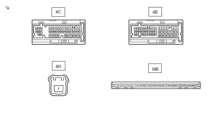
| *a | Component without harness connected (Power Distribution Box Assembly) | - | - |
(a) Remove the main body ECU (multiplex network body ECU) from the power distribution box assembly.
Click here

(b) Measure the resistance according to the value(s) in the table below.
Standard Resistance:
| Tester Connection | Condition | Specified Condition |
|---|---|---|
| 4B-36 - MB-13 (GND1) | Always | Below 1 Ω |
| 4C-41 - MB-14 (GND2) | Always | Below 1 Ω |
| 4H-1 - MB-27 (IGR) | Auxiliary battery not connected to 4C-17 - 4B-36 or 4C-41 | 10 kΩ or higher |
| 4H-1 - MB-27 (IGR) | Auxiliary battery positive (+) → 4C-17 Auxiliary battery negative (-) → 4B-36 or 4C-41 | Below 1 Ω |
| OK |
 | REPLACE MAIN BODY ECU (MULTIPLEX NETWORK BODY ECU) |
| NG |
 | REPLACE POWER DISTRIBUTION BOX ASSEMBLY |
 Data List / Active Test
DATA LIST / ACTIVE TEST DATA LIST NOTICE: In the following table, the values listed under "Normal Condition" are reference values. Do not depend solely on these reference values when deciding whether a part is faulty or not...
 Front Door Courtesy Switch Circuit
DESCRIPTION The main body ECU (multiplex network body ECU) detects the condition of the front door courtesy light switch assembly. WIRING DIAGRAM
CAUTION / NOTICE / HINT NOTICE: Before replacing the main body ECU (multiplex network body ECU), refer to Registration...
Other information:
Toyota Yaris XP210 (2020-2025) Reapir and Service Manual: Vehicle Control History
VEHICLE CONTROL HISTORY FUNCTION OVERVIEW (a) The vehicle control history is a function that records control data (record data) when triggered by specific vehicle behavior or user input. Checking the vehicle control history may provide, quantitative diagnostic information that can be used as a reference to proceed with a malfunction diagnosis...
Toyota Yaris XP210 (2020-2025) Reapir and Service Manual: Disassembly
DISASSEMBLY CAUTION / NOTICE / HINT NOTICE: Before installation of each part, thoroughly clean and dry it. Then apply grease or oil as necessary. Do not use alkaline chemicals to clean aluminum parts, rubber parts or precoated bolts. Also, do not use non-residue solvent or other cleaning oils to clean O-rings, oil seals or rubber parts...
Categories
- Manuals Home
- Toyota Yaris Owners Manual
- Toyota Yaris Service Manual
- G16e-gts (engine Mechanical)
- How to use USB mode
- Fuse Panel Description
- New on site
- Most important about car
Break-In Period
No special break-in is necessary, but a few precautions in the first 600 miles (1,000 km) may add to the performance, economy, and life of the vehicle.
Do not race the engine. Do not maintain one constant speed, either slow or fast, for a long period of time. Do not drive constantly at full-throttle or high engine rpm for extended periods of time. Avoid unnecessary hard stops. Avoid full-throttle starts.