Toyota Yaris: Lin Communication System / How To Proceed With Troubleshooting
CAUTION / NOTICE / HINT
HINT:
- Use the following procedure to troubleshoot the LIN communication system.
- *: Use the GTS.
PROCEDURE
| 1. | VEHICLE BROUGHT TO WORKSHOP |
|

| 2. | CUSTOMER PROBLEM ANALYSIS |
HINT:
- In troubleshooting, confirm that the problem symptoms have been accurately identified. Preconceptions should be discarded in order to make an accurate judgment. To clearly understand what the problem symptoms are, it is extremely important to ask the customer about the problem and the conditions at the time the malfunction occurred.
- Gather as much information as possible for reference. Past problems that seem unrelated may also help in some cases.
- The following 5 items are important points for problem analysis:
| What | Vehicle model, system name |
| When | Date, time, occurrence frequency |
| Where | Road conditions |
| Under what conditions? | Driving conditions, weather conditions |
| How did it happen? | Problem symptoms |
|

| 3. | PRE-CHECK |
(a) Measure the auxiliary battery voltage with the ignition switch off.
Standard Voltage:
11 to 14 V
If the voltage is below 11 V, recharge or replace the auxiliary battery before proceeding to the next step.
(b) Check the fuses and relays.
(c) Check the connectors and terminals to make sure that there are no abnormalities such as a loose connection or deformation.
|

| 4. | INSPECT COMMUNICATION FUNCTION OF CAN COMMUNICATION SYSTEM* |
(a) Using the GTS, check for CAN communication system DTCs.
Click here

| Result | Proceed to |
|---|---|
| CAN DTCs are not output | A |
| CAN DTCs are output | B |
| B |
 | GO TO CAN COMMUNICATION SYSTEM |
|

| 5. | INSPECT COMMUNICATION FUNCTION OF LIN COMMUNICATION SYSTEM* |
(a) Using the GTS, check for LIN communication system DTCs.
Click here

| Result | Proceed to |
|---|---|
| LIN DTCs are not output | A |
| LIN DTCs are output | B |
| B |
 | GO TO DIAGNOSTIC TROUBLE CODE CHART |
|

| 6. | OVERALL ANALYSIS AND TROUBLESHOOTING* |
(a) Terminals of ECU
Click here

(b) Data List / Active Test
Click here

|

| 7. | REPAIR OR REPLACE |
|

| 8. | CONFIRMATION TEST |
| NEXT |
 | END |
 System Description
SYSTEM DESCRIPTION LIN COMMUNICATION SYSTEM DESCRIPTION The LIN communication system is used for communication between the components in the tables below...
 Terminals Of Ecu
TERMINALS OF ECU CHECK POWER DISTRIBUTION BOX ASSEMBLY AND MAIN BODY ECU (MULTIPLEX NETWORK BODY ECU)
*1 POWER DISTRIBUTION BOX ASSEMBLY *2 MAIN BODY ECU (MULTIPLEX NETWORK BODY ECU) (a) Remove main body ECU (multiplex network body ECU)...
Other information:
Toyota Yaris XP210 (2020-2025) Reapir and Service Manual: Propeller Shaft System
Problem Symptoms TablePROBLEM SYMPTOMS TABLE HINT: Use the table below to help determine the cause of problem symptoms. If multiple suspected areas are listed, the potential causes of the symptoms are listed in order of probability in the "Suspected Area" column of the table...
Toyota Yaris XP210 (2020-2025) Reapir and Service Manual: Removal
REMOVAL CAUTION / NOTICE / HINT HINT: Use the same procedure for the RH side and LH side. The following procedure is for the LH side. PROCEDURE 1. REMOVE FRONT DOOR LOWER FRAME BRACKET GARNISH Click here 2. REMOVE MULTIPLEX NETWORK MASTER SWITCH ASSEMBLY WITH FRONT ARMREST BASE UPPER PANEL (for Driver Side) Click here 3...
Categories
- Manuals Home
- Toyota Yaris Owners Manual
- Toyota Yaris Service Manual
- Key Battery Replacement
- How to use USB mode
- To Set Speed
- New on site
- Most important about car
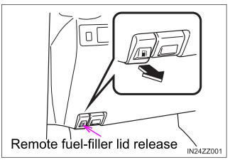
Refueling
Before refueling, close all the doors, windows, and the liftgate/trunk lid, and switch the ignition OFF.
To open the fuel-filler lid, pull the remote fuel-filler lid release.