Toyota Yaris: Power Steering System / Fail-safe Chart
Toyota Yaris XP210 (2020-2025) Reapir and Service Manual / Steering / Power Assist Systems / Power Steering System / Fail-safe Chart
FAIL-SAFE CHART
If a problem occurs in the power steering system, the power steering assist will be stopped or the amount of power assist will be decreased to protect the system.
Power Steering System| Malfunction | Fail-safe Operation | EPS warning light | Buzzer |
|---|---|---|---|
| Power steering assist stops or assist amount is limited | Red or yellow | Sounds intermittently or once |
| Power steering assist is temporarily limited | Yellow | Sounds once |
HINT:
- If the power steering assist stops, the EPS warning light comes on (red).
- If the amount of power assist is reduced, the EPS warning light comes on (yellow) and a vibration or sound may occur.
- The amount of power assist may be decreased to prevent the motor and ECUs from overheating if the steering wheel is continuously turned when the vehicle is either stopped or being driven at a low speed, or if the steering wheel is kept at either full lock position for a long time. In such cases, the amount of power assist returns to normal when the steering wheel is not turned for approximately 10 minutes with the engine running.
- If the auxiliary battery is not sufficiently charged or the voltage decreases temporarily, the amount of power assist will be reduced and the EPS warning light will come on. In such cases, the amount of power assist returns to normal when the auxiliary battery voltage recovers.
 Freeze Frame Data
FREEZE FRAME DATA FREEZE FRAME DATA NOTICE:
It is difficult to show the specified values (judgment values) clearly because freeze frame data values change significantly due to differences in measurement conditions, surroundings, or vehicle conditions...
 Data List / Active Test
DATA LIST / ACTIVE TEST DATA LIST HINT: Using the GTS to read the Data List allows the values or states of switches, sensors, actuators and other items to be read without removing any parts...
Other information:
Toyota Yaris XP210 (2020-2025) Reapir and Service Manual: Installation
INSTALLATION PROCEDURE 1. INSTALL NO. 1 CONVERTER CONTROL BRACKET (a) Install the No. 1 converter control bracket to the eco run vehicle converter assembly with the 2 bolts. 2. INSTALL ECO RUN VEHICLE CONVERTER ASSEMBLY (a) Install the eco run vehicle converter assembly with the bolt and nut...
Toyota Yaris XP210 (2020-2025) Reapir and Service Manual: Thermostat
ComponentsCOMPONENTS ILLUSTRATION *1 WATER INLET WITH THERMOSTAT SUB-ASSEMBLY *2 GASKET N*m (kgf*cm, ft.*lbf): Specified torque ● Non-reusable part RemovalREMOVAL CAUTION / NOTICE / HINT The necessary procedures (adjustment, calibration, initialization, or registration) that must be performed after parts are removed, installed, or replaced during the water inlet with thermostat sub-assembly removal/installation are shown below...
Categories
- Manuals Home
- Toyota Yaris Owners Manual
- Toyota Yaris Service Manual
- Fuse Panel Description
- Engine Start Function When Key Battery is Dead
- G16e-gts (engine Mechanical)
- New on site
- Most important about car
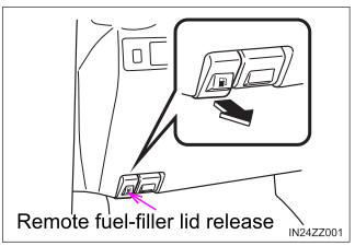
Refueling
Before refueling, close all the doors, windows, and the liftgate/trunk lid, and switch the ignition OFF.
To open the fuel-filler lid, pull the remote fuel-filler lid release.

Copyright © 2025 www.toyaris4.com
