Toyota Yaris: Manual Transaxle System / Dtc Check / Clear
DTC CHECK / CLEAR
CHECK DTC (Using GTS)
(a) DTCs which are stored in the ECM can be output to the GTS.
(1) Connect the GTS to the DLC3.
(2) Turn the ignition switch to ON.
(3) Turn the GTS on.
(4) Enter the following menus: Powertrain / Engine / Trouble Codes.
Powertrain > Engine > Trouble Codes(5) Confirm the DTCs and freeze frame data, and then write them down.
(6) Confirm the details of the DTCs.
Click here

CLEAR DTC (Using GTS)
(a) Connect the GTS to the DLC3.
(b) Turn the ignition switch to ON.
(c) Turn the GTS on.
(d) Enter the following menus: Powertrain / Engine / Trouble Codes.
(e) Clear the DTCs.
Powertrain > Engine > Clear DTCsCLEAR DTC (without Using GTS)
(a) Perform either of the following operations.
NOTICE:
After turning ignition switch off, waiting time may be required before disconnecting the cable from the negative (-) auxiliary battery terminal. Therefore, make sure to read the disconnecting the cable from the negative (-) auxiliary battery terminal notices before proceeding with work.
Click here

(1) Disconnect the cable from the negative (-) auxiliary battery terminal for more than 1 minute.
(2) Remove the EFI NO. 1 fuses from the No. 1 engine room relay block located inside the engine compartment for more than 1 minute.
 Diagnosis System
DIAGNOSIS SYSTEM EURO-OBD (EUROPEAN SPEC) (a) When troubleshooting Europe On-Board Diagnostic (Euro-OBD) vehicles, an OBD scan tool (complying with ISO 15765-4) must be connected to the vehicle...
 Freeze Frame Data
FREEZE FRAME DATA DESCRIPTION
The ECM records vehicle and driving condition information as freeze frame data the moment a DTC is stored. When troubleshooting, freeze frame data can be helpful in determining whether the vehicle was moving or stationary, whether the engine was warmed up or not, whether the air fuel ratio was lean or rich, as well as other data recorded at the time of a malfunction...
Other information:
Toyota Yaris XP210 (2020-2025) Reapir and Service Manual: Evaporative Emission System Purge Control Valve "A" Circuit Open (P044313)
DESCRIPTION To reduce hydrocarbon (HC) emissions, evaporated fuel from the fuel tank is routed through a charcoal canister to the intake manifold for combustion in the cylinders. The ECM changes the duty signals to the purge VSV (Vacuum Switching Valve for Purge Control) so that the intake amount of hydrocarbon (HC) emissions is appropriate for the driving conditions (engine load, engine speed, vehicle speed, etc...
Toyota Yaris XP210 (2020-2025) Reapir and Service Manual: Installation
INSTALLATION PROCEDURE 1. INSTALL CLUTCH MASTER CYLINDER ASSEMBLY (a) Install a new clutch master cylinder gasket to the clutch master cylinder assembly. (b) Install the clutch master cylinder assembly to the vehicle body with the 2 nuts. Torque: 12...
Categories
- Manuals Home
- Toyota Yaris Owners Manual
- Toyota Yaris Service Manual
- Headlights
- Brake System Control Module "A" System Voltage System Voltage Low (C137BA2)
- How to connect USB port/Auxiliary jack
- New on site
- Most important about car
Keys

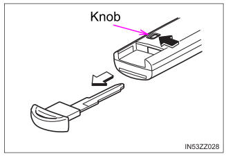
To use the auxiliary key, press the knob and pull out the auxiliary key from the smart key.

