Toyota Yaris: Seat Belt Warning System / Customize Parameters
CUSTOMIZE PARAMETERS
CUSTOMIZE SEAT BELT WARNING SYSTEM
NOTICE:
- When the customer requests a change in a function, first make sure that the function can be customized.
- Be sure to make a note of the current settings before customizing.
- When troubleshooting a function, first make sure that the function is set to the default setting.
- These buzzers should be ON for safe driving. Perform this procedure only if it is necessary to set the buzzer to OFF (disabled).
(a) Customizing with the GTS
(1) Select the setting by referring to the table below.
Warning| Tester Display | Description | Default | Setting | ECU |
|---|---|---|---|---|
| Driver Seatbelt Warning Buzzer Function | Enables sounding of the driver seat belt warning buzzer | ON | $00:OFF,$01:ON | Combination meter assembly |
| Passenger Seatbelt Warning Buzzer Function | Enables sounding of the front passenger seat belt warning buzzer | ON | $00:OFF,$01:ON | Combination meter assembly |
| Rear Right Seatbelt Warning Buzzer Function | Function to sound the rear RH seat belt warning buzzer | ON | $00:OFF,$01:ON | Combination meter assembly |
| Rear Left Seatbelt Warning Buzzer Function | Function to sound the rear LH seat belt warning buzzer | ON | $00:OFF,$01:ON | Combination meter assembly |
HINT:
This setting is only valid when the vehicle is driven at 20 km/h (12 mph) or more.
 How To Proceed With Troubleshooting
CAUTION / NOTICE / HINT HINT:
Use the following procedure to troubleshoot the seat belt warning system.
*: Use the GTS.
PROCEDURE 1. VEHICLE BROUGHT TO WORKSHOP
NEXT
2...
 Problem Symptoms Table
PROBLEM SYMPTOMS TABLE HINT:
Use the table below to help determine the cause of problem symptoms. If multiple suspected areas are listed, the potential causes of the symptoms are listed in order of probability in the "Suspected Area" column of the table...
Other information:
Toyota Yaris XP210 (2020-2025) Reapir and Service Manual: Trouble in Passenger Airbag ON/OFF Indicator
DESCRIPTION This circuit detects the airbag cut off switch cylinder sub-assembly status. The passenger airbag ON/OFF indicator comes on to inform the driver of the instrument panel passenger without door airbag assembly status (activated or deactivated)...
Toyota Yaris XP210 (2020-2025) Reapir and Service Manual: Removal
REMOVAL CAUTION / NOTICE / HINT The necessary procedures (adjustment, calibration, initialization, or registration) that must be performed after parts are removed, installed, or replaced during the instrument panel passenger without door airbag assembly removal/installation are shown below...
Categories
- Manuals Home
- Toyota Yaris Owners Manual
- Toyota Yaris Service Manual
- Speedometer, Odometer, Trip Meter and Trip Meter Selector
- Fuse Panel Description
- How to use USB mode
- New on site
- Most important about car
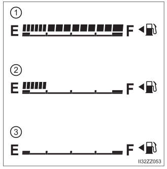
Fuel Gauge
The fuel gauge shows approximately how much fuel is remaining in the tank when the ignition is switched ON. We recommend keeping the tank over 1/4 full.