Toyota Yaris: Wiper And Washer System / Terminals Of Ecu
TERMINALS OF ECU
CHECK MAIN BODY ECU (MULTIPLEX NETWORK BODY ECU) AND POWER DISTRIBUTION BOX ASSEMBLY

| *1 | Power Distribution Box Assembly | *2 | Main Body ECU (Multiplex Network Body ECU) |
(a) Remove the main body ECU (multiplex network body ECU) from the power distribution box assembly.
(b) Measure the voltage and resistance according to the value(s) in the table below.
| Terminal No. (Symbol) | Terminal Description | Condition | Specified Condition |
|---|---|---|---|
| MB-26 (BCEU) - Body ground | Auxiliary battery power supply | Ignition switch off | 11 to 14 V |
| MB-27 (IGR) - Body ground | IG power source | Ignition switch off | Below 1 V |
| Ignition switch ON | 11 to 14 V | ||
| MB-13 (GND1) - Body ground | Ground | Always | Below 1 Ω |
(c) Install the main body ECU (multiplex network body ECU) to power distribution box assembly.
(d) Measure the voltage and check for pulses according to the value(s) in the table below.
| Terminal No. (Symbol) | Terminal Description | Condition | Specified Condition |
|---|---|---|---|
| 4D-5 - Body ground | CXPI communication line | Ignition switch ON | Pulse generation |
| H4-6 (WPS) - Body ground | Wiper Relay operation signal | Less than approximately 60 seconds after ignition switch turned off | 11 to 14 V |
| Approximately 60 seconds or more after ignition switch turned off | Below 1 V | ||
| H5-11 (LIN4) - Body ground | LIN communication line | Ignition switch ON | Pulse generation |
CHECK WINDSHIELD WIPER RELAY ASSEMBLY

(a) Disconnect the A50 and A49 windshield wiper relay assembly connectors.
(b) Measure the voltage and resistance according to the value(s) in the table below.
| Terminal No. (Symbol) | Terminal Description | Condition | Specified Condition |
|---|---|---|---|
| A50-3 (E) - Body ground | Ground | Always | Below 1 Ω |
| A50-5 (EWS) - Body ground | Ground | Always | Below 1 Ω |
| A50-6 (IGWS) - Body ground | Washer circuit IG power source | Ignition switch off | Below 1 V |
| Ignition switch ON | 11 to 14 V | ||
| A50-8 (+B) - Body ground | Ignition switch ON signal (Power source circuit) | Ignition switch ON | 11 to 14 V |
| Less than approximately 60 seconds after ignition switch turned off | |||
| Approximately 60 seconds or more after ignition switch turned off | Below 1 V | ||
| A49-5 (ES) - Body ground | Ground | Always | Below 1 Ω |
(c) Connect the A50 and A49 windshield wiper relay assembly connectors.
(d) Measure the voltage and resistance and check for pulses according to the value(s) in the table below.
| Terminal No. (Symbol) | Terminal Description | Condition | Specified Condition |
|---|---|---|---|
| A50-1 (+WR) - Body ground | Front washer operation signal | Ignition switch ON, front washer operating | 11 to 14 V |
| A50-2 (+1) - Body ground | LO operation signal to windshield wiper motor assembly | Ignition switch ON, windshield wiper motor assembly operating in LO | 11 to 14 V |
| A50-4 (+2) - Body ground | HI operation signal to windshield wiper motor assembly | Ignition switch ON, windshield wiper motor assembly operating in HI | 11 to 14 V |
| A49-3 (2S) - Body ground | Windshield wiper motor assembly HI operation signal | Windshield wiper motor assembly stopped | 4.5 to 5.5 V |
| Windshield wiper motor assembly operating in HI | Below 1 V | ||
| A49-4 (MPX1) - Body ground | CXPI communication line | Ignition switch ON | Pulse generation |
| Less than approximately 100 seconds after ignition switch turned off | |||
| Approximately 100 seconds or more after ignition switch turned off | 11 to 14 V | ||
| A49-6 (+SM) - Body ground | Windshield wiper motor assembly position detection signal | Windshield wiper motor assembly in LO or HI operation | Below 1 V ←→ 11 to 14V |
| Windshield wiper motor assembly stopped | Below 1 V |
CHECK RAIN SENSOR

(a) Disconnect the V9 rain sensor connector.
(b) Measure the voltage and resistance and check for pulses according to the value(s) in the table below.
| Terminal No. (Symbol) | Terminal Description | Condition | Specified Condition |
|---|---|---|---|
| V9-2 (ES) - Body ground | Ground | Always | Below 1 Ω |
| V9-3 (MPX) - Body ground | LIN communication signal | Ignition switch ON | Pulse generation |
| V9-4 (SIG) - Body ground | IG power source circuit | Ignition switch off | Below 1 V |
| Ignition switch ON | 11 to 14 V |
 Problem Symptoms Table
PROBLEM SYMPTOMS TABLE NOTICE: If the main body ECU (multiplex network body ECU) is replaced, refer to the Registration. Click here
HINT:
Use the table below to help determine the cause of problem symptoms...

Other information:
Toyota Yaris XP210 (2020-2026) Reapir and Service Manual: Diagnostic Trouble Code Chart
D..
Toyota Yaris XP210 (2020-2026) Reapir and Service Manual: Vehicle Control History
VEHICLE CONTROL HISTORY NOTICE: When checking the vehicle control history, first record the output codes and after clearing the history, check the output history again. CHECK VEHICLE CONTROL HISTORY (ACTIVE TORQUE SPLIT AWD SYSTEM) (a) According to the display on the GTS, check the vehicle control history...
Categories
- Manuals Home
- Toyota Yaris Owners Manual
- Toyota Yaris Service Manual
- Engine & Hybrid System
- G16e-gts (engine Mechanical)
- Key Battery Replacement
- New on site
- Most important about car
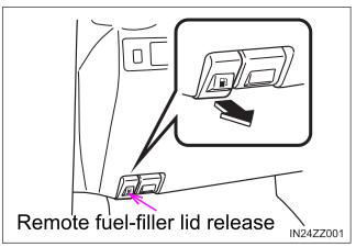
Refueling
Before refueling, close all the doors, windows, and the liftgate/trunk lid, and switch the ignition OFF.
To open the fuel-filler lid, pull the remote fuel-filler lid release.