Toyota Yaris: Cxpi Communication System / Terminals Of Ecu
TERMINALS OF ECU
NOTICE:
-
After the ignition switch is turned off, there may be a waiting time before disconnecting the negative (-) auxiliary battery terminal.
Click here

-
When disconnecting and reconnecting the auxiliary battery, there is an automatic learning function that completes learning when the respective system is used.
Click here

CHECK POWER DISTRIBUTION BOX ASSEMBLY AND MAIN BODY ECU (MULTIPLEX NETWORK BODY ECU)
(a) Remove the main body ECU (multiplex network body ECU).
Click here


| *1 | Power Distribution Box Assembly | *2 | Main Body ECU (Multiplex Network Body ECU) |
(b) Reconnect the power distribution box assembly connectors.
Click here

(c) Measure the voltage and resistance according to the value(s) in the table below.
| Terminal No. (Symbol) | Terminal Description | Condition | Specified Condition |
|---|---|---|---|
| MB-13 (GND1) - Body ground | Ground | Always | Below 1 Ω |
| MB-26 (BECU) - Body ground | Auxiliary battery power supply | Ignition switch off | 11 to 14 V |
| MB-27 (IGR) - Body ground | IG power supply | Ignition switch off | Below 1 V |
| Ignition switch ON | 11 to 14 V |
(d) Install the main body ECU (multiplex network body ECU).
Click here

(e) Measure the voltage and check for pulses according to the value(s) in the table below.
| Terminal No. (Symbol) | Terminal Description | Condition | Specified Condition |
|---|---|---|---|
| 4D-5 - Body ground | CXPI communication line | Ignition switch ON | Pulse generation |
| 4E-43 - Body ground | Rear window defogger signal (output) | Rear window defogger switch off | Below 1.5 V |
| Rear window defogger switch on | 8 to 14 V | ||
| 4B-2 - Body ground | Mirror heater drive signal (output) | Rear window defogger switch off | Below 1.5 V |
| Rear window defogger switch on | 8 to 14 V | ||
| 4C-10 - Body ground | Power return mirror motor drive signal (output) | Outer rear view mirror assembly moves to the return position. | Below 1.5 V |
| Outer rear view mirror assembly not move. | 8 to 14 V | ||
| 4C-21 - Body ground | Power retract mirror motor drive signal (output) | Outer rear view mirror assembly moves to the retract position | Below 1.5 V |
| Outer rear view mirror assembly not move | 8 to 14 V |
SEMICONDUCTOR POWER INTEGRATION ECU

(a) Disconnect the cable from the negative (-) auxiliary battery terminal.
(b) Disconnect the A85 and A86 semiconductor power integration ECU connectors.
(c) Connect the cable to the negative (-) auxiliary battery terminal.
(d) Measure the resistance and voltage according to the value(s) in the table below.
| Terminal No. (Symbol) | Terminal Description | Condition | Specified Condition |
|---|---|---|---|
| A85-1 (+B) - Body ground | Auxiliary battery power supply | Ignition switch off | 8 to 14 V |
| A86-5 (-S) - Body ground | Light control LED ECU RH operation signal input | Headlight not illuminated | 6 V or higher |
| Headlight illuminated | Below 1.7 V | ||
| A86-16 (GND2) - Body ground | Ground | Always | Below 1 Ω |
| A86-20 (IG) - Body ground | IG power supply | Ignition switch off | Below 1.5 V |
| Ignition switch ON | 8 to 14 V | ||
| A86-24 (-S) - Body ground | Light control LED ECU LH operation signal input | Headlight not illuminated | 6 V or higher |
| Headlight illuminated | Below 1.7 V | ||
| A86-26 (GND1) - Body ground | Ground | Always | Below 1 Ω |
(e) Reconnect the A85 and A86 semiconductor power integration ECU connectors.
(f) Measure the voltage and check for pulses according to the value(s) in the table below.
| Terminal No. (Symbol) | Terminal Description | Condition | Specified Condition |
|---|---|---|---|
| A86-8 (CXPI) - Body ground | CXPI communication line | Ignition switch ON | Pulse generation |
| A86-1 (L) - Body ground | Light control LED ECU LH operation signal output | Headlight not illuminated | Below 3.0 V |
| Headlight illuminated | 8 V or higher | ||
| A86-2 (L)- Body ground | Light control LED ECU RH operation signal output | Headlight not illuminated | Below 3.0 V |
| Headlight illuminated | 8 V or higher | ||
| A86-17 (L) - Body ground | Front fog light RH operation signal output | Front fog light not illuminated | Below 3.0 V |
| Front fog light illuminated | 8 V or higher | ||
| A86-18 (L) - Body ground | Front fog light LH operation signal output | Front fog light not illuminated | Below 3.0 V |
| Front fog light illuminated | 8 V or higher |
 How To Proceed With Troubleshooting
CAUTION / NOTICE / HINT HINT:
Use these procedures to troubleshoot the CXPI communication system.
*: Use the GTS.
PROCEDURE 1. VEHICLE BROUGHT TO WORKSHOP
NEXT
2...
 Dtc Check / Clear
DTC CHECK / CLEAR CHECK DTC (a) Enter the following menus: Body Electrical / Main Body / Trouble Codes. (b) Check for DTCs. Body Electrical > Main Body > Trouble Codes CLEAR DTC (a) Enter the following menus: Body Electrical / Main Body / Clear DTCs...
Other information:
Toyota Yaris XP210 (2020-2025) Owner's Manual: Hazardous Driving
When driving on ice or in water, snow, mud, sand, or similar hazards: Be cautious and allow extra distance for braking. Avoid sudden braking and sudden maneuvering. Do not pump the brakes. Continue to press down on the brake pedal. Refer to Antilock Brake System (ABS)...
Toyota Yaris XP210 (2020-2025) Owner's Manual: Cup Holder
WARNING Never use a cup holder to hold hot liquids while the vehicle is moving Using a cup holder to hold hot liquids while the vehicle is moving is dangerous. If the contents spill, you could be scalded. Do not put anything other than cups or drink cans in cup holders Putting objects other than cups or drink cans in a cup holder is dangerous...
Categories
- Manuals Home
- Toyota Yaris Owners Manual
- Toyota Yaris Service Manual
- Engine & Hybrid System
- Opening and Closing the Liftgate/Trunk Lid
- Starting the Engine
- New on site
- Most important about car
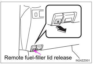
Refueling
Before refueling, close all the doors, windows, and the liftgate/trunk lid, and switch the ignition OFF.
To open the fuel-filler lid, pull the remote fuel-filler lid release.