Toyota Yaris: Exterior Panels / Trim / Tail Gate Protector
Components
COMPONENTS
ILLUSTRATION

| *1 | ROOF TOP MOULDING SUB-ASSEMBLY | - | - |
Removal
REMOVAL
PROCEDURE
1. REMOVE ROOF HEADLINING
Click here
.gif)
2. REMOVE ROOF TOP MOULDING SUB-ASSEMBLY
| (a) Remove the nut. |
|

| (b) Apply protective tape around the roof top moulding sub-assembly. |
|

| (c) Disengage the clips to remove the roof top moulding sub-assembly as shown in the illustration. |
|

Installation
INSTALLATION
PROCEDURE
1. INSTALL ROOF TOP MOULDING SUB-ASSEMBLY
| (a) Engage the clips to install the roof top moulding sub-assembly as shown in the illustration. |
|
.png)
(b) Install the nut.
(c) Remove the protective tape.
2. INSTALL ROOF HEADLINING
Click here
.gif)
 Installation
INSTALLATION CAUTION / NOTICE / HINT NOTICE:
Work indoors with less dust and wind.
Install the roof outside cover in an environment where the temperature is 20 to 30°C (68 to 86°F)...

Other information:
Toyota Yaris XP210 (2020-2025) Reapir and Service Manual: ABS Pump Motor Control Circuit Voltage Out of Range (C052C1C)
DESCRIPTION DTC No. Detection Item DTC Detection Condition Trouble Area DTC Output from C052C1C ABS Pump Motor Control Circuit Voltage Out of Range Any of the following is detected: When the +BS terminal voltage is from 9.5 to 17...
Toyota Yaris XP210 (2020-2025) Reapir and Service Manual: Terminals Of Ecu
TERMINALS OF ECU *1 Power Distribution Box Assembly *2 Main Body ECU (Multiplex Network Body ECU) CHECK POWER DISTRIBUTION BOX ASSEMBLY AND MAIN BODY ECU (MULTIPLEX NETWORK BODY ECU) (a) Remove the main body ECU (multiplex network body ECU) from the power distribution box assembly...
Categories
- Manuals Home
- Toyota Yaris Owners Manual
- Toyota Yaris Service Manual
- Engine Start Function When Key Battery is Dead
- Fuel Gauge
- How to use USB mode
- New on site
- Most important about car
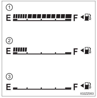
Fuel Gauge
The fuel gauge shows approximately how much fuel is remaining in the tank when the ignition is switched ON. We recommend keeping the tank over 1/4 full.