Toyota Yaris: Air Fuel Ratio Sensor (for Sensor 2) / Removal
REMOVAL
CAUTION / NOTICE / HINT
The necessary procedures (adjustment, calibration, initialization, or registration) that must be performed after parts are removed, installed, or replaced during the No. 2 air fuel ratio sensor removal/installation are shown below.
Necessary Procedure After Parts Removed/Installed/Replaced| Replacement Part or Procedure | Necessary Procedure | Effect/Inoperative when not Performed | Link |
|---|---|---|---|
| Inspection after repair |
|
|

CAUTION:
-
When the engine is hot, do not touch high-temperature areas such as the engine or exhaust pipe.

- Touching high-temperature areas such as the engine and exhaust pipe could result in burns.
PROCEDURE
1. REMOVE CENTER NO. 4 ENGINE UNDER COVER
Click here

2. REMOVE CENTER FRONT FLOOR BRACE
Click here

3. REMOVE CENTER NO. 1 FLOOR BRACE
Click here

4. REMOVE NO. 2 AIR FUEL RATIO SENSOR
| (a) Disconnect the No. 2 air fuel ratio sensor connector. |
|

(b) Disengage the 3 wire harness clamps.
| (c) Using SST, remove the No. 2 air fuel ratio sensor from the front exhaust pipe assembly. SST: 09224-00012 NOTICE: If the No. 2 air fuel ratio sensor has been struck or dropped, replace it. |
|

 Components
COMPONENTS ILLUSTRATION
*1 NO. 2 AIR FUEL RATIO SENSOR *2 CENTER NO. 1 FLOOR BRACE *3 CENTER FRONT FLOOR BRACE *4 CENTER NO. 4 ENGINE UNDER COVER
N*m (kgf*cm, ft...
 Inspection
INSPECTION PROCEDURE 1. INSPECT NO. 2 AIR FUEL RATIO SENSOR (a) Measure the resistance according to the value(s) in the table below. Standard Resistance: Tester Connection Condition Specified Condition D109-1(HA1B) - D109-2(+B) 20°C (68°F) 1...
Other information:
Toyota Yaris XP210 (2020-2025) Reapir and Service Manual: Terminals Of Ecu
TERMINALS OF ECU CHECK POWER DISTRIBUTION BOX ASSEMBLY AND MAIN BODY ECU (MULTIPLEX NETWORK BODY ECU) *1 POWER DISTRIBUTION BOX ASSEMBLY *2 MAIN BODY ECU (MULTIPLEX NETWORK BODY ECU) (a) Remove main body ECU (multiplex network body ECU)...
Toyota Yaris XP210 (2020-2025) Reapir and Service Manual: On-vehicle Inspection
ON-VEHICLE INSPECTION PROCEDURE 1. INSPECT BRAKE BOOSTER ASSEMBLY (a) Airtightness check (1) Start the engine and stop it after 1 or 2 minutes. Slowly depress the brake pedal several times. HINT: If the brake pedal can be depressed nearly to the floor the first time, but on the 2nd and 3rd time cannot be depressed as far, the brake booster assembly is airtight...
Categories
- Manuals Home
- Toyota Yaris Owners Manual
- Toyota Yaris Service Manual
- Maintenance
- Opening and Closing the Liftgate/Trunk Lid
- Fuel Gauge
- New on site
- Most important about car
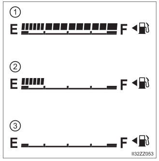
Fuel Gauge
The fuel gauge shows approximately how much fuel is remaining in the tank when the ignition is switched ON. We recommend keeping the tank over 1/4 full.