Toyota Yaris: Lighting (int) / Personal Light
Components
COMPONENTS
ILLUSTRATION

| *1 | MAP LIGHT ASSEMBLY | - | - |
Removal
REMOVAL
PROCEDURE
1. REMOVE MAP LIGHT ASSEMBLY
(a) Using a moulding remover D, disengage the clips to remove the map light assembly as shown in the illustration.

 | Remove in this Direction |
| (b) Disconnect the connector. |
|

Inspection
INSPECTION
PROCEDURE
1. INSPECT MAP LIGHT ASSEMBLY
(a) Check the map light.
| (1) Apply auxiliary battery voltage to the map light assembly and check that the map light comes on. OK:
If the result is not as specified, replace the map light assembly. |
|

(b) Check the door switch.
| (1) Measure the resistance according to the value(s) in the table below. Standard Resistance:
If the result is not as specified, replace the map light assembly. |
|

Installation
INSTALLATION
PROCEDURE
1. INSTALL MAP LIGHT ASSEMBLY
(a) Connect the connector.
(b) Engage the clips to install the map light assembly as shown in the illustration.

 | Install in this Direction |
 Door Unlock Detection Switch Circuit
DESCRIPTION The main body ECU (multiplex network body ECU) detects the condition of each door unlock detection switch. WIRING DIAGRAM
CAUTION / NOTICE / HINT NOTICE: Before replacing the main body ECU (multiplex network body ECU), refer to Registration...
 Room Light
ComponentsCOMPONENTS ILLUSTRATION
*1 NO. 1 ROOM LIGHT ASSEMBLY *2 NO. 1 ROOM LIGHT BULB *3 NO. 1 ROOM LIGHT LENS *4 NO. 1 ROOM LIGHT HOUSING RemovalREMOVAL PROCEDURE 1...
Other information:
Toyota Yaris XP210 (2020-2025) Reapir and Service Manual: Components
COMPONENTS ILLUSTRATION *1 FRONT AXLE ASSEMBLY *2 FRONT AXLE SHAFT NUT *3 FRONT DISC *4 FRONT DISC BRAKE CALIPER ASSEMBLY *5 FRONT DRIVE SHAFT ASSEMBLY *6 FRONT LOWER NO. 1 SUSPENSION ARM SUB-ASSEMBLY *7 FRONT SPEED SENSOR *8 TIE ROD END SUB-ASSEMBLY *9 COTTER PIN *10 FRONT SHOCK ABSORBER ASSEMBLY *11 FRONT FLEXIBLE HOSE *12 STEERING KNUCKLE SEAL *13 INNER NO...
Toyota Yaris XP210 (2020-2025) Reapir and Service Manual: Data List / Active Test
DATA LIST / ACTIVE TEST DATA LIST NOTICE: In the table below, the values listed under "Normal Condition" are reference values. Do not depend solely on these reference values when deciding whether a part is faulty or not. HINT: Using the GTS to read the Data List allows the values or states of switches, sensors, actuators and other items to be read without removing any parts...
Categories
- Manuals Home
- Toyota Yaris Owners Manual
- Toyota Yaris Service Manual
- Starting the Engine
- Key Battery Replacement
- Removal
- New on site
- Most important about car
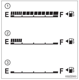
Fuel Gauge
The fuel gauge shows approximately how much fuel is remaining in the tank when the ignition is switched ON. We recommend keeping the tank over 1/4 full.