Toyota Yaris: Air Conditioning System / Operation not Accepted Even If Air Conditioning Switch is Operated
DESCRIPTION
If the air conditioning system cannot be operated using the air conditioning control assembly, the following factors may be the cause.
| Symptom | Factor |
|---|---|
| Air conditioning system cannot be operated using air conditioning control assembly
|
|
WIRING DIAGRAM

CAUTION / NOTICE / HINT
NOTICE:
Inspect the fuses for circuits related to this system before performing the following procedure.
PROCEDURE
| 1. | CHECK FOR DTC |
(a) Clear the DTCs.
Body Electrical > Air Conditioner > Clear DTCs(b) Check for DTCs.
Body Electrical > Air Conditioner > Trouble Codes| Result | Proceed to |
|---|---|
| B14B287 is not output | A |
| B14B287 is output | B |
| B |
 | GO TO DTC B14B287 |
|

| 2. | CHECK HARNESS AND CONNECTOR (AIR CONDITIONING AMPLIFIER ASSEMBLY - POWER SOURCE AND BODY GROUND) |
(a) Disconnect the air conditioning amplifier assembly connector.
| (b) Measure the voltage and resistance according to the value(s) in the table below. Standard Voltage:
Standard Resistance:
|
|

| OK |
 | REPLACE AIR CONDITIONING AMPLIFIER ASSEMBLY |
| NG |
 | REPAIR OR REPLACE HARNESS OR CONNECTOR |
 Cooling is Poor
DESCRIPTION If the cooling effect of the air conditioning system is weak, the following factors may be the cause. Symptom Factor
Cooling effectiveness is poor
Cooling response is slow
ECO drive mode function (air flow volume is restricted due to ECO drive mode being selected)
Compressor with pulley assembly malfunction
Refrigerant volume (high)
Refrigerant volume (low)
Clogged cooler condenser assembly fins
Cooling fan system malfunction
Mechanical locking of damper and damper link
Automatic light control sensor malfunction
High inlet air temperature
PROCEDURE 1...
 Front Window Fogging
DESCRIPTION If the windshield frequently fogs up even though the air conditioning system is operating, the following factors may be the cause. Symptom Factor Windshield frequently fogs up
Compressor malfunction
Refrigerant volume (low)
Cooler expansion valve (opened excessively)
No...
Other information:
Toyota Yaris XP210 (2020-2025) Reapir and Service Manual: On-vehicle Inspection
ON-VEHICLE INSPECTION PROCEDURE 1. INSPECT MASS AIR FLOW METER HINT: Perform "Inspection After Repair" after replacing the mass air flow meter. Click here (a) Read the value of Data List item "Mass Air Flow Sensor" using the GTS. NOTICE: Perform the inspection of the mass air flow meter while it is installed to the air cleaner cap sub-assembly (installed to the vehicle)...
Toyota Yaris XP210 (2020-2025) Reapir and Service Manual: Diagnostic Trouble Code Chart
D..
Categories
- Manuals Home
- Toyota Yaris Owners Manual
- Toyota Yaris Service Manual
- Diagnostic Trouble Code Chart
- Brake System Control Module "A" System Voltage System Voltage Low (C137BA2)
- Removal
- New on site
- Most important about car
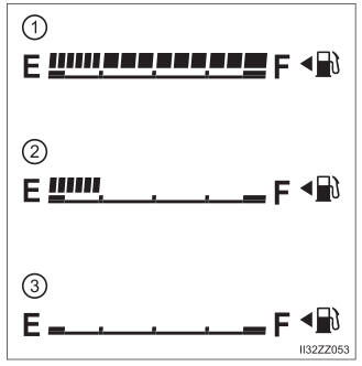
Fuel Gauge
The fuel gauge shows approximately how much fuel is remaining in the tank when the ignition is switched ON. We recommend keeping the tank over 1/4 full.