Toyota Yaris: Sfi System / Internal Control Module Accelerator Pedal Position Performance Internal Electronic Failure (P060D49)
MONITOR DESCRIPTION
The ECM monitors the input signals of the No. 1 accelerator pedal position sensor. If the input signals and control signals deviate, this DTC is stored.
| DTC No. | Detection Item | DTC Detection Condition | Trouble Area | MIL | Note |
|---|---|---|---|---|---|
| P060D49 | Internal Control Module Accelerator Pedal Position Performance Internal Electronic Failure | Either of the following conditions is met (1 trip detection logic):
| ECM | Comes on | SAE: P060D |
MONITOR STRATEGY
| Required Sensors/Components | ECM |
| Frequency of Operation | Continuous |
CONFIRMATION DRIVING PATTERN
- Connect the GTS to the DLC3.
- Turn the ignition switch to ON.
- Turn the GTS on.
- Clear the DTCs (even if no DTCs are stored, perform the clear DTC procedure).
- Turn the GTS off.
- Turn the ignition switch off.
- Disconnect the GTS.
- Disconnect the cable from the negative (-) auxiliary battery terminal and wait for 1 minute.
- Connect the cable to the negative (-) auxiliary battery terminal.
- Connect the GTS to the DLC3.
- Turn the ignition switch to ON.
- Turn the GTS on.
- Wait 16 seconds or more.
- Enter the following menus: Powertrain / Engine / Trouble Codes.
-
Read the pending DTCs.
HINT:
- If a pending DTC is output, the system is malfunctioning.
- If a pending DTC is not output, perform the following procedure.
- Enter the following menus: Powertrain / Engine / Utility / All Readiness.
- Input the DTC: P060D49.
-
Check the DTC judgment result.
GTS Display
Description
NORMAL
- DTC judgment completed
- System normal
ABNORMAL
- DTC judgment completed
- System abnormal
INCOMPLETE
- DTC judgment not completed
- Perform driving pattern after confirming DTC enabling conditions
HINT:
- If the judgment result is NORMAL, the system is normal.
- If the judgment result is ABNORMAL, the system is malfunctioning.
CAUTION / NOTICE / HINT
NOTICE:
-
After the ignition switch is turned off, there may be a waiting time before disconnecting the negative (-) auxiliary battery terminal.
Click here

-
When disconnecting and reconnecting the auxiliary battery.
HINT:
When disconnecting and reconnecting the auxiliary battery, there is an automatic learning function that completes learning when the respective system is used.
HINT:
Read Freeze Frame Data using the GTS. The ECM records vehicle and driving condition information as Freeze Frame Data the moment a DTC is stored. When troubleshooting, Freeze Frame Data can help determine if the vehicle was moving or stationary, if the engine was warmed up or not, if the air fuel ratio was lean or rich, and other data from the time the malfunction occurred.
PROCEDURE
| 1. | CLEAR DTC |
(a) Clear the DTCs.
Powertrain > Engine > Clear DTCs(b) Turn the ignition switch off.
|

| 2. | READ OUTPUT DTC (DTC P060D49) |
(a) Disconnect the cable from the negative (-) auxiliary battery terminal and wait for 1 minute.
(b) Connect the cable to the negative (-) auxiliary battery terminal.
(c) Wait 16 seconds or more.
(d) Read the DTCs.
Powertrain > Engine > Trouble Codes| Result | Proceed to |
|---|---|
| DTCs are not output | A |
| P060D49 is output | B |
| A |
 | CHECK FOR INTERMITTENT PROBLEMS |
| B |
 | REPLACE ECM |
 Control Module Performance Bank 1 Watchdog/Safety MCU Failure (P060747,P060787)
MONITOR DESCRIPTION The ECM continuously monitors its internal ICs and the monitor IC. If the monitor IC is abnormal, the ECM illuminates the MIL and stores DTC P060747...
 Internal Control Module Throttle Position Performance Internal Electronic Failure (P060E49)
MONITOR DESCRIPTION The ECM monitors the signals received from the No. 1 throttle position sensor. As the ECM monitors the VTA1 signal of the No. 1 throttle position sensor, if these signals do not correlate, a DTC will be stored...
Other information:
Toyota Yaris XP210 (2020-2024) Reapir and Service Manual: Inspection
INSPECTION PROCEDURE 1. INSPECT TURN SIGNAL SWITCH (a) Check the resistance. (1) Measure the resistance according to the value(s) in the table below. Standard Resistance: Light Control Switch Tester Connection Condition Specified Condition z6-7 (A) - z6-5 (EL) Light control switch in AUTO position Below 1 Ω z6-3 (T) - z6-5 (EL) Light control switch in tail position Below 1 Ω z6-12 (H) - z6-5 (EL) Light control switch in head position Below 1 Ω Dimmer Passing Switch Tester Connection Condition Specified Condition z6-11 (HF) - z6-5 (EL) Dimmer switch in high flash position Below 1 Ω z6-16 (HU) - z6-5 (EL) Dimmer switch in high position Below 1 Ω Fog Light Switch Tester Connection Condition Specified Condition z6-4 (B) - z6-5 (EL) Fog light switch in rear position Below 1 Ω z6-13 (BFG) - z6-5 (EL) Fog light switch in front position Below 1 Ω Turn Signal Switch Tester Connection Condition Specified Condition z6-8 (TR) - z6-5 (EL) Turn signal switch in neutral position 10 kΩ or higher z6-14 (TL) - z6-5 (EL) Turn signal switch in neutral position 10 kΩ or higher z6-8 (TR) - z6-5 (EL) Turn signal switch in right turn position Below 1 Ω z6-8 (TR) - z6-5 (EL) Turn signal switch in full right turn position Below 1 Ω z6-8 (TR) - z6-6 (CR) Turn signal switch in full right turn position Below 1 Ω z6-6 (CR) - z6-5 (EL) Turn signal switch in full right turn position Below 1 Ω z6-14 (TL) - z6-5 (EL) Turn signal switch in left turn position Below 1 Ω z6-14 (TL) - z6-5 (EL) Turn signal switch in full left turn position Below 1 Ω z6-14 (TL) - z6-6 (CR) Turn signal switch in full left turn position Below 1 Ω z6-6 (CR) - z6-5 (EL) Turn signal switch in full left turn position Below 1 Ω If the result is not as specified, replace the turn signal switch...
Toyota Yaris XP210 (2020-2024) Reapir and Service Manual: Components
COMPONENTS ILLUSTRATION *1 EQUALIZER STEREO COMPONENT COVER *2 STEREO COMPONENT EQUALIZER ASSEMBLY *3 STEREO COMPONENT EQUALIZER ASSEMBLY WITH BRACKET *4 NO. 1 EQUALIZER STEREO COMPONENT BRACKET *5 NO. 2 EQUALIZER STEREO COMPONENT BRACKET - - N*m (kgf*cm, ft...
Categories
- Manuals Home
- Toyota Yaris Owners Manual
- Toyota Yaris Service Manual
- Fuel Gauge
- How to connect USB port/Auxiliary jack
- Low Engine Coolant Temperature Indicator Light (Blue)
- New on site
- Most important about car
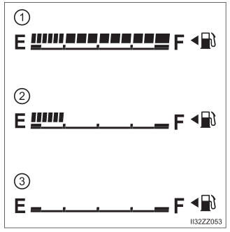
Fuel Gauge
The fuel gauge shows approximately how much fuel is remaining in the tank when the ignition is switched ON. We recommend keeping the tank over 1/4 full.