Toyota Yaris: Axle And Differential / Differential Oil Temperature Sensor
Components
COMPONENTS
ILLUSTRATION

| *1 | TEMPERATURE SENSOR | *2 | GASKET |
| *3 | TAIL EXHAUST PIPE ASSEMBLY | - | - |
 | Tightening torque for "Major areas involving basic vehicle performance such as moving/turning/stopping" : N*m (kgf*cm, ft.*lbf) |
 | N*m (kgf*cm, ft.*lbf): Specified torque |
| * | For use with union nut wrench | ● | Non-reusable part |
Removal
REMOVAL
CAUTION / NOTICE / HINT
The necessary procedures (adjustment, calibration, initialization or registration) that must be performed after parts are removed and installed, or replaced during the temperature sensor removal/installation are shown below.
Necessary Procedures After Parts Removed/Installed/Replaced| Replaced Part or Performed Procedure | Necessary Procedure | Effect/Inoperative Function when Necessary Procedure not Performed | Link |
|---|---|---|---|
| Gas leaks from exhaust system | Inspection After Repair |
|
|
CAUTION:
To prevent burns, do not touch the engine, exhaust pipe or other high temperature components while the engine is hot.

PROCEDURE
1. REMOVE TAIL EXHAUST PIPE ASSEMBLY
Click here

2. REMOVE TEMPERATURE SENSOR
| (a) Disconnect the temperature sensor connector. |
|
| (b) Using SST, remove the temperature sensor and gasket. SST: 09729-00220 |
|
Inspection
INSPECTION
PROCEDURE
1. INSPECT TEMPERATURE SENSOR
| (a) Measure the resistance according to the value(s) in the table below. Standard Resistance:
If the result is not as specified, replace the temperature sensor. |
|
Installation
INSTALLATION
PROCEDURE
1. INSTALL TEMPERATURE SENSOR
| (a) Using SST, install a new gasket and temperature sensor. Torque: Specified tightening torque : 30 N·m {306 kgf·cm, 22 ft·lbf} SST: 09729-00220 HINT:
|
|
(b) Connect the temperature sensor connector.
2. INSTALL TAIL EXHAUST PIPE ASSEMBLY
Click here

3. INSPECT FOR EXHAUST GAS LEAK
Click here

 Differential Oil
ComponentsCOMPONENTS ILLUSTRATION
*1 REAR DIFFERENTIAL DRAIN PLUG *2 REAR DIFFERENTIAL FILLER PLUG *3 GASKET - -
Tightening torque for "Major areas involving basic vehicle performance such as moving/turning/stopping": N*m (kgf*cm, ft...
 Differential System
PrecautionPRECAUTION
Before disassembly, clean the outside of the differential assembly and remove any sand or mud to prevent it from entering the inside of the assembly during disassembly and installation...
Other information:
Toyota Yaris XP210 (2020-2025) Reapir and Service Manual: Starter Relay Circuit Current Above Threshold (P061519)
DESCRIPTION When the engine is started by stop and start control, the engine stop and start ECU controls the starter assembly by activating the ST NO. 1 relay (for starter pinion operation) via voltage from terminal STA. If overcurrent is detected in the starter relay circuit, the engine stop and start ECU stores DTC P061519 and blinks the stop and start cancel indicator...
Toyota Yaris XP210 (2020-2025) Owner's Manual: Low Engine Coolant Temperature Indicator Light (Blue)
The light illuminates continuously when the engine coolant temperature is low and turns off after the engine is warm. If the low engine coolant temperature indicator light remains illuminated after the engine has been sufficiently warmed up, the temperature sensor could have a malfunction...
Categories
- Manuals Home
- Toyota Yaris Owners Manual
- Toyota Yaris Service Manual
- Diagnostic Trouble Code Chart
- Removal
- Opening and Closing the Liftgate/Trunk Lid
- New on site
- Most important about car
Keys

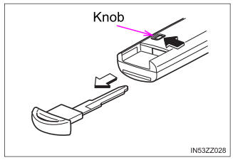
To use the auxiliary key, press the knob and pull out the auxiliary key from the smart key.


