Toyota Yaris: Fuel Pump / Installation
INSTALLATION
PROCEDURE
1. INSTALL FUEL SUCTION WITH PUMP AND GAUGE TUBE ASSEMBLY
(a) Install a new gasket to the fuel tank assembly.
(b) Connect the fuel return vent tube sub-assembly to the fuel suction tube with pump and gauge assembly.
Click here


| *1 | Fuel Return Vent Tube Sub-assembly |
 | Front of the Vehicle |
- Make sure to correctly assemble the fuel return vent tube sub-assembly as shown in the illustration. If assembled incorrectly, the fuel sender gauge assembly (No. 2 fuel sender gauge assembly) may catch on the fuel return vent tube resulting in incorrect operation of the fuel sender gauge assembly (No. 2 fuel sender gauge assembly) and an incorrect value being displayed on the fuel gauge.
- When connecting the fuel tube connector, do not excessively pull on the fuel return vent tube sub-assembly.
(c) Insert the fuel suction tube with pump and gauge assembly to the fuel tank assembly as shown in the illustration.
NOTICE:
- Be careful not to bend the arm of the fuel sender gauge assembly.
- To avoid applying excessive force to the tip of the fuel sender gauge assembly, tilt the fuel sub-tank sub-assembly diagonally and insert it into the fuel tank assembly as shown in the illustration.

| *1 | Plate Sub-assembly | *2 | Fuel Sub-tank Sub-assembly |
| *3 | Fuel Sender Gauge Assembly | - | - |
| (d) Align the protrusions of the fuel suction with pump and gauge tube assembly with the notches in the fuel tank assembly. |
|

2. INSTALL FUEL PUMP GAUGE RETAINER
(a) Install the fuel pump gauge retainer.
(1) While pressing down on the fuel suction with pump and gauge tube assembly, temporarily install the fuel pump gauge retainer.
| (2) Temporarily install SST (plate) and SST (claw) to the fuel pump gauge retainer. SST: 09808-14031 09808-01030 09808-01090 SST: 09808-01071 HINT: Securely insert the ends of SST (claw) into the insertion points in the fuel pump gauge retainer. |
|

(3) While firmly pressing SST (claw) into the insertion points in the fuel pump gauge retainer, tighten SST (bolt).
(4) Install SST (handle) to SST (plate).
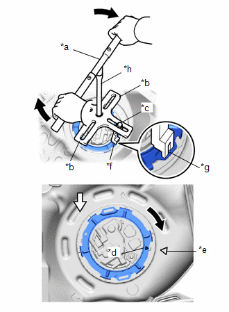
| *a | SST (Handle) |
| *b | SST (Plate) |
| *c | SST (Bolt) |
| *d | Triangle Mark (Fuel Pump Gauge Retainer) |
| *e | Triangle Mark (Fuel Tank Assembly) |
| *f | SST (Claw) |
| *g | Insertion Point |
| *h | Extension Bar |
 | Front Side of Vehicle |
SST: 09808-14031
09808-01010
09808-01030
09808-01090
SST: 09808-01071
(5) Using SST, rotate the fuel pump gauge retainer so that the triangle mark on the fuel pump gauge retainer is aligned with the triangle mark on the fuel tank assembly to install the fuel suction with pump and gauge tube assembly to the fuel tank assembly.
NOTICE:
- Do not use any tools other than specified as this may result in damage to the fuel pump gauge retainer or fuel tank assembly.
- Do not press down on SST excessively as this may make the fuel pump gauge retainer hard to rotate, and may damage components.
- Make sure to rotate SST (handle) horizontally. If it is rotated at an angle, SST may come off.
- Do not spin SST too fast or use an impact wrench as this may result in damage to components.
- If SST comes off of the fuel pump gauge retainer, loosen SST (bolt) and reinstall SST.
- Make sure that the fuel suction tube set gasket does not come off.
(b) Attach the claw and install the No. 1 fuel tube clamp to the fuel pump gauge retainer.
3. INSTALL NO. 1 FUEL TUBE CLAMP
(a) Engage the claw and install the No. 1 fuel tube clamp to the fuel pump gauge retainer.
4. CONNECT FUEL TANK MAIN TUBE SUB-ASSEMBLY
(a) Push the fuel tube joint of the fuel tank main tube sub-assembly, and install the tube joint clip.

| *1 | Plate Sub-assembly | *2 | Tube Joint Clip |
| *3 | Fuel Tank Main Tube Sub-assembly | - | - |
| *a | O-ring | *b | Correct |
| *c | Incorrect | *d | Fuel Tube Joint |
 | Insert |
 | Insert |
NOTICE:
- Check that there are no scratches or foreign matter around the connecting parts of the fuel tube joint and plug before performing this work.
- Check that the fuel tube joint is securely inserted to the end.
- Check that the tube joint clip is on the collar of the fuel tube joint.
- After installing the tube joint clip, check that the fuel tank main tube sub-assembly is securely connected by pulling on it.
5. CONNECT CHARCOAL CANISTER OUTLET HOSE
(a) Connect the charcoal canister outlet hose to the fuel suction with pump and gauge tube assembly.
6. CONNECT FUEL TANK EVAP TUBE SUB-ASSEMBLY
(a) Connect the fuel tank evap tube sub-assembly to the fuel suction with pump and gauge tube assembly.
Click here

7. CONNECT NO. 1 FUEL EVAPORATION TUBE SUB-ASSEMBLY
| (a) Connect the No. 1 fuel evaporation tube sub-assembly to the fuel suction with pump and gauge tube assembly, and slide the clamp to secure the tube. |
|

8. INSTALL REAR FLOOR SERVICE HOLE COVER (for LH Side)
(a) Remove any remaining butyl tape from the rear floor service hole cover and body.
(b) Connect the 2 connectors to the fuel suction with pump and gauge tube assembly.
(c) Install the rear floor service hole cover with new butyl tape.
NOTICE:
Securely install the rear floor service hole cover.
9. CONNECT CABLE TO NEGATIVE AUXILIARY BATTERY TERMINAL
Click here

10. INITIALIZATION AFTER RECONNECTING AUXILIARY BATTERY TERMINAL
HINT:
When disconnecting and reconnecting the auxiliary battery, there is an automatic learning function that completes learning when the respective system is used.
Click here

11. INSPECT FOR FUEL LEAK
Click here

12. INSTALL BENCH TYPE REAR SEAT CUSHION ASSEMBLY
Click here

13. PERFORM INITIALIZATION
(a) Perform "Inspection After Repair" after replacing the fuel pump.
Click here

 Reassembly
REASSEMBLY PROCEDURE 1. INSTALL FUEL PUMP HINT: Perform "Inspection After Repair" after replacing the fuel pump. Click here
(a) Install the fuel pump to the No...

Other information:
Toyota Yaris XP210 (2020-2024) Reapir and Service Manual: Installation
INSTALLATION PROCEDURE 1. INSTALL STARTER ASSEMBLY (a) Install the wire harness clamp bracket to the starter assembly with the bolt. Torque: 10 N·m {102 kgf·cm, 7 ft·lbf} (b) Install the starter assembly to the cylinder block sub-assembly with the 2 bolts...
Toyota Yaris XP210 (2020-2024) Owner's Manual: To Set Speed
Activate the cruise control system by pressing the ON switch. The cruise main indication (white) is displayed. Accelerate to the desired speed, which must be more than 16 mph (25 km/h). Set the cruise control by pressing the SET/- switch at the desired speed...
Categories
- Manuals Home
- Toyota Yaris Owners Manual
- Toyota Yaris Service Manual
- Diagnostic Trouble Code Chart
- Fuse Panel Description
- Speedometer, Odometer, Trip Meter and Trip Meter Selector
- New on site
- Most important about car
Fuel-Filler Lid and Cap
WARNING
When removing the fuel-filler cap, loosen the cap slightly and wait for any hissing to stop, then remove it
Fuel spray is dangerous. Fuel can burn skin and eyes and cause illness if ingested. Fuel spray is released when there is pressure in the fuel tank and the fuel-filler cap is removed too quickly.