Toyota Yaris: Rear Brake / Reassembly
REASSEMBLY
PROCEDURE
1. TEMPORARILY TIGHTEN REAR DISC BRAKE BLEEDER PLUG
(a) Temporarily tighten the rear disc brake bleeder plug to the rear disc brake cylinder.
HINT:
Fully tighten the rear disc brake bleeder plug after bleeding the system.
2. INSTALL REAR DISC BRAKE BLEEDER PLUG CAP
(a) Install the rear disc brake bleeder plug cap to the rear disc brake bleeder plug.
3. INSTALL PISTON SEAL
(a) Apply lithium soap base glycol grease to the entire circumference of 2 new piston seals.

 | Lithium Soap Base Glycol Grease |
| (b) Install the 2 piston seals to the rear disc brake cylinder. NOTICE:
|
|

4. INSTALL CYLINDER BOOT
(a) Apply a light layer of lithium soap base glycol grease to the inner surfaces of 2 new cylinder boots.

 | Lithium Soap Base Glycol Grease |
(b) Apply a light layer of lithium soap base glycol grease to the contact surfaces of the 2 rear disc brake pistons.
| (c) Install the 2 cylinder boots to the 2 rear disc brake pistons. NOTICE: Securely install the cylinder boot into the groove of the rear disc brake piston. |
|

5. INSTALL REAR DISC BRAKE PISTON
| (a) Install the 2 rear disc brake pistons to the rear disc brake cylinder. NOTICE: Do not forcibly install the rear disc brake piston into the rear disc brake cylinder. |
|

| (b) Push in the 2 cylinder boots and engage the 2 cylinder boots to each retainer of the rear disc brake cylinder. NOTICE:
|
|

 Inspection
INSPECTION PROCEDURE 1. INSPECT BRAKE CYLINDER AND PISTON (a) Check the rear disc brake cylinder bore and rear disc brake piston for rust and scoring. If necessary, replace the rear disc brake cylinder assembly and rear disc brake piston...
 Installation
INSTALLATION CAUTION / NOTICE / HINT HINT:
Use the same procedure for the RH side and LH side.
The following procedure is for the LH side.
PROCEDURE 1...
Other information:
Toyota Yaris XP210 (2020-2025) Reapir and Service Manual: Disposal
DISPOSAL CAUTION / NOTICE / HINT CAUTION: Always use a cloth to prevent shards of metal from flying about due to the release of pressurized gas. Always wear safety glasses. HINT: The gas is colorless, odorless and non-poisonous. PROCEDURE 1...
Toyota Yaris XP210 (2020-2025) Reapir and Service Manual: Removal
REMOVAL CAUTION / NOTICE / HINT HINT: When the cable is disconnected / reconnected to the auxiliary battery terminal, systems temporarily stop operating. However, each system has a function that completes learning the first time the system is used. Learning completes when vehicle is driven Effect/Inoperative Function When Necessary Procedures are not Performed Necessary Procedures Link Lane tracing assist system Drive the vehicle straight ahead at 35 km/h (22 mph) or more for 5 second or more...
Categories
- Manuals Home
- Toyota Yaris Owners Manual
- Toyota Yaris Service Manual
- Fuel Gauge
- Headlights
- Diagnostic Trouble Code Chart
- New on site
- Most important about car
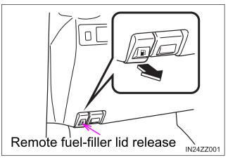
Refueling
Before refueling, close all the doors, windows, and the liftgate/trunk lid, and switch the ignition OFF.
To open the fuel-filler lid, pull the remote fuel-filler lid release.