Toyota Yaris: Turbocharger / Installation
INSTALLATION
PROCEDURE
1. INSTALL STUD BOLT
(a) Using an E8 "TORX" socket wrench, install the stud bolt to the turbocharger sub-assembly.
Torque:
10 N·m {102 kgf·cm, 7 ft·lbf}
2. INSTALL TURBO WATER PIPE GASKET
(a) Install the new turbo water pipe gasket to the turbocharger sub-assembly.
3. INSTALL NO. 1 TURBO WATER PIPE SUB-ASSEMBLY
(a) Install the No. 1 turbo water pipe sub-assembly to the turbocharger sub-assembly with the 2 bolts.
Torque:
10 N·m {102 kgf·cm, 7 ft·lbf}
4. CONNECT TURBO OIL INLET PIPE SUB-ASSEMBLY
(a) Install a new gasket to the turbo water pipe sub-assembly.
(b) Install the turbo water pipe sub-assembly to the turbocharger sub-assembly with the bolt.
Torque:
35 N·m {357 kgf·cm, 26 ft·lbf}
5. CONNECT COMPRESSOR INLET ELBOW
(a) Install a new gasket to the compressor inlet elbow.
(b) Install the compressor inlet elbow to the turbocharger sub-assembly with the bolt and nut.
Torque:
21 N·m {214 kgf·cm, 15 ft·lbf}
6. INSTALL STUD BOLT
Click here

7. INSTALL EXHAUST MANIFOLD TO HEAD GASKET
(a) Install a new exhaust manifold to head gasket to the cylinder head sub-assembly.
8. INSTALL TURBOCHARGER SUB-ASSEMBLY
(a) Install the collar to the turbocharger sub-assembly with the red side facing the rear of the vehicle.

| *a | Color(Red) |
 | Rear Side |
 | Front Side |
(b) Tighten the 7 nuts in the order shown in the illustration.
Torque:
44.3 N·m {452 kgf·cm, 33 ft·lbf}
9. CONNECT WIRE HARNESS
(a) Connect the connector to the turbocharger sub-assembly.
10. CONNECT NO. 1 TURBO WATER PIPE SUB-ASSEMBLY
(a) Install a new gasket to the inlet No. 1 turbo water pipe sub-assembly.
(b) Install the No. 1 turbo water pipe sub-assembly to the cylinder block sub-assembly with the bolt and union bolt.
Torque:
Bolt :
13 N·m {133 kgf·cm, 10 ft·lbf}
Union Bolt :
35 N·m {357 kgf·cm, 26 ft·lbf}
(c) Connect the turbo water hose to the No. 1 turbo water pipe sub-assembly and slide the clip to secure it.
11. INSTALL TURBO OIL INLET PIPE UNION BOLT
(a) Install a new gasket to the inlet turbo oil pipe sub-assembly.
(b) Install the inlet turbo oil pipe sub-assembly to the cylinder block sub-assembly with the union bolt.
Torque:
35 N·m {357 kgf·cm, 26 ft·lbf}
12. INSTALL NO. 2 VACUUM TRANSMITTING HOSE
(a) Connect the No. 2 vacuum transmitting hose.
13. INSTALL NO. 2 AIR HOSE
| (a) Install the new No. 2 air hose to the turbocharger sub-assembly and tighten the hose clamp. Torque: 6.0 N·m {61 kgf·cm, 53 in·lbf} |
|

14. CONNECT TURBO OIL OUTLET PIPE
(a) Install a new gasket to the outlet turbo oil pipe.
(b) Install the outlet turbo oil pipe to the turbocharger sub-assembly with the 2 bolts.
Torque:
10 N·m {102 kgf·cm, 7 ft·lbf}
15. INSTALL NO. 1 TURBO INSULATOR
(a) Install the No. 1 turbo insulator to the turbocharger sub-assembly with the 3 bolts.
Torque:
21 N·m {214 kgf·cm, 15 ft·lbf}
16. INSTALL NO. 1 AIR INLET DUCT
| (a) Install the No. 1 air inlet duct to the compressor inlet elbow and tighten the hose clamp. Torque: 3.0 N·m {31 kgf·cm, 27 in·lbf} |
|

(b) Install the No. 1 air inlet duct to the No. 1 air hose and tighten the hose clamp.
Torque:
4.0 N·m {41 kgf·cm, 35 in·lbf}
(c) Install the No. 1 air inlet duct to the cylinder head sub-assembly with the bolt.
Torque:
10 N·m {102 kgf·cm, 7 ft·lbf}
(d) Connect the ventilation hose to the No. 1 air inlet duct and slide the clip to secure it.
17. INSTALL INTAKE AIR RESONATOR
(a) Install the intake air resonator to the No. 1 air hose and tighten the hose clamp.
Torque:
3.0 N·m {31 kgf·cm, 27 in·lbf}
(b) Install the intake air resonator to the air cleaner hose assembly and tighten the hose clamp.
Torque:
3.0 N·m {31 kgf·cm, 27 in·lbf}
(c) Install the intake air resonator to the cylinder head sub-assembly with the 2 bolts.
Torque:
21 N·m {214 kgf·cm, 15 ft·lbf}
18. INSTALL AIR CLEANER CASE SUB-ASSEMBLY
(a) Engage the 3 grommets and pin to install the air cleaner case sub-assembly.
(b) Engage the 6 clamps.
(c) Connect the 3 connector.
19. CONNECT NO. 1 AIR CLEANER HOSE
(a) Connect the No. 1 air cleaner hose to the air cleaner case sub-assembly and tighten the hose clamp.
Torque:
3.0 N·m {31 kgf·cm, 27 in·lbf}
20. INSTALL NO. 1 AIR CLEANER INLET
(a) Install the No.1 air cleaner inlet with 2 clips
21. INSTALL DASH PANEL HEAT INSULATOR
(a) Install the dash panel heat insulator to the vehicle body with the 3 nuts and clamp.
Torque:
5.0 N·m {51 kgf·cm, 44 in·lbf}
22. INSTALL OUTER COWL TOP PANEL SUB-ASSEMBLY
Click here

23. INSTALL NO. 1 FRONT VENTILATOR SEAL
Click here

24. INSTALL WATER GUARD PLATE RH
Click here

25. INSTALL WINDSHIELD WIPER MOTOR AND LINK
Click here

26. INSTALL EXHAUST MANIFOLD CONVERTER SUB-ASSEMBLY
Click here

27. ADD ENGINE COOLANT
Click here

28. INSPECT FOR COOLANT LEAK
Click here

29. ADD ENGINE OIL
Click here

30. CHECK ENGINE OIL LEVEL
Click here

31. INSPECT FOR ENGINE OIL LEAK
Click here

32. CHECK ENGINE OIL LEVEL
Click here

 Inspection
INSPECTION PROCEDURE 1. INSPECT TURBOCHARGER SUB-ASSEMBLY (a) Check if the compressor side impeller and exhaust side turbine are damaged or defective...

Other information:
Toyota Yaris XP210 (2020-2025) Reapir and Service Manual: Microwave Integrated Circuit (VCO Circuit) in Front Radar Sensor Internal Electronic Failure (C1A8749-C1A8987,C1A8C08)
DESCRIPTION When an internal malfunction is detected in the millimeter wave radar sensor assembly, a DTC is stored. DTC No. Detection Item DTC Detection Condition Trouble Area C1A8749 Microwave Integrated Circuit (VCO Circuit) in Front Radar Sensor Internal Electronic Failure When the ignition switch is ON, the millimeter wave radar sensor assembly detects a malfunction in the microwave integrated circuit (VCO circuit)...
Toyota Yaris XP210 (2020-2025) Reapir and Service Manual: Utility
U..
Categories
- Manuals Home
- Toyota Yaris Owners Manual
- Toyota Yaris Service Manual
- Diagnostic Trouble Code Chart
- Removal
- Engine & Hybrid System
- New on site
- Most important about car
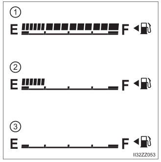
Fuel Gauge
The fuel gauge shows approximately how much fuel is remaining in the tank when the ignition is switched ON. We recommend keeping the tank over 1/4 full.