Toyota Yaris: ABS/TCS/DSC / Dynamic Stability Control (DSC)
The Dynamic Stability Control (DSC) automatically controls braking and engine torque in conjunction with systems such as ABS and TCS to help control side slip when driving on slippery surfaces, or during sudden or evasive maneuvering, enhancing vehicle safety. Refer to ABS and TCS.
DSC operation is possible at speeds greater than 12 mph (20 km/h).
The warning light turns on when the system has a malfunction. Refer to Contact Your Toyota Dealer and Have Vehicle Inspected.
WARNING
Do not rely on the Dynamic Stability Control as a substitute for safe driving
The Dynamic Stability Control (DSC) cannot compensate for unsafe and reckless driving, excessive speed, tailgating (following another vehicle too closely), and hydroplaning (reduced tire friction and road contact because of water on the road surface). You can still have an accident.
NOTICE
- The DSC may not operate correctly unless the following are
observed:
- Use tires of the correct size specified for your Toyota on all 4 wheels.
- Use tires of the same manufacturer, brand and tread pattern on all 4 wheels.
- Do not mix worn tires.
- The DSC may not operate correctly when tire chains are used or a temporary spare tire is installed because the tire diameter changes.
 Traction Control System (TCS)
The Traction Control System (TCS) enhances traction and safety
by controlling engine torque and braking. When the TCS detects
driving wheel slippage, it lowers engine torque and operates the
brakes to prevent loss of traction...
 TCS/DSC Indicator Light
This indicator light stays on for a
few seconds when the ignition is
switched ON. If the TCS or DSC is
operating, the indicator light
flashes...
Other information:
Toyota Yaris XP210 (2020-2025) Reapir and Service Manual: Customize Parameters
C..
Toyota Yaris XP210 (2020-2025) Reapir and Service Manual: Reassembly
REASSEMBLY PROCEDURE 1. INSTALL FRONT BUMPER LOWER ABSORBER (a) Install the 4 grommets. (b) Engage the claws to install the front bumper lower absorber. (c) Install the clip and 5 screws. 2. INSTALL NO. 1 ENGINE UNDER COVER ASSEMBLY Click here 3...
Categories
- Manuals Home
- Toyota Yaris Owners Manual
- Toyota Yaris Service Manual
- Speedometer, Odometer, Trip Meter and Trip Meter Selector
- Fuel Gauge
- Brake System Control Module "A" System Voltage System Voltage Low (C137BA2)
- New on site
- Most important about car
Keys

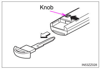
To use the auxiliary key, press the knob and pull out the auxiliary key from the smart key.

