Toyota Yaris: Airbag System / VEHICLE CONTROL HISTORY (RoB)
VEHICLE CONTROL HISTORY (RoB)
NOTICE:
- Replacing or repairing related components may cause vehicle control history codes to be stored.
- When checking the vehicle control history, make sure to record the output histories. Then, clear the histories and recheck the output histories again.
CHECK VEHICLE CONTROL HISTORY (AIRBAG SYSTEM)
(a) Following the instructions on the GTS, display the vehicle control history (RoB) check screen and read the codes.
Body Electrical > SRS Airbag > Utility| Tester Display |
|---|
| Vehicle Control History (RoB) |
| Warning Light | Code | Tester Display | Measurement Item | Diagnostic Note |
|---|---|---|---|---|
| SRS warning light illuminated | X210B | SRS Airbag ECU IG Voltage Drop | History of SRS becoming inoperable due to decreased voltage of airbag sensor assembly IG power supply. | Recorded when the airbag sensor assembly input voltage is continuously less than 8 V for 60 seconds. Click here
|
| - | X210C | Satellite Sensor During Reset | History of SRS becoming inoperable due to satellite sensor communication reset. | Recorded when satellite sensor communication stops and a reset is performed. Check that satellite sensor DTCs are not being output. |
| SRS warning light illuminated | XF01B | ECU Security Key Not Registered | Incomplete registration of the ECU security key |
|


CLEAR VEHICLE CONTROL HISTORY (AIRBAG SYSTEM)
(a) Select the deletion button on the vehicle control history (RoB) check screen and clear the codes.
Body Electrical > SRS Airbag > Utility| Tester Display |
|---|
| Vehicle Control History (RoB) |
 Vehicle Control History
VEHICLE CONTROL HISTORY FUNCTION OVERVIEW (a) The vehicle control history is a function that records control data (record data) when triggered by specific vehicle behavior or user input...
 Driver Frontal Stage 1 Deployment Control Circuit Short to Ground (B000111)
DESCRIPTION DTC No. Detection Item DTC Detection Condition Trouble Area Warning Indicate Test Mode / Check Mode B000111 Driver Frontal Stage 1 Deployment Control Circuit Short to Ground
The airbag sensor assembly detects a short to ground in the driver seat airbag squib circuit for 0...
Other information:
Toyota Yaris XP210 (2020-2024) Reapir and Service Manual: MIL Circuit
DESCRIPTION The Malfunction Indicator Lamp (MIL) is used to indicate vehicle malfunctions detected by the ECM. The MIL operation can be checked visually. When the ignition switch is first turned to ON, the MIL should be illuminated and should then turn off after the engine is started...
Toyota Yaris XP210 (2020-2024) Reapir and Service Manual: System Description
SYSTEM DESCRIPTION LOAD OPERATION OUTPUT (a) Load is turned on or off according to the operation signals and switch signals from each ECU. Components Semiconductor Power Integration ECU Power Distribution Box Assembly Operation Signal Communication Support *1: w/ Front Seat Heater *2: Built into power distribution box assembly Headlight ECU Assembly ○ - Not supported Fog Light Assembly ○ - Supported Rear Window Defogger / Mirror Heater - ○ Supported Taillight - ○ Supported Rear Fog Light - ○ Supported Back-up Light - ○ Not supported Outer Rear View Mirror Assembly - ○ Supported Panel Illumination - ○ Supported Seat Heater LH*1 High/Low - ○ Not supported Seat Heater RH*1 High/Low - ○ Not supported Passenger Seat Buckle Switch Delegated Input - ○ - Occupant Detection Sensor Delegated Input - ○ - Rear Seat RH Buckle Switch Delegated Input - ○ - Rear Seat CTR Buckle Switch Delegated Input - ○ - Rear Seat LH Buckle Switch Delegated Input - ○ - IGR Relay*2 - ○ Not supported SEMICONDUCTOR FUSE FUNCTION (a) When a malfunction current occurs during load operation, the current is shut off before the electrical lines emit smoke, and then load is turned off...
Categories
- Manuals Home
- Toyota Yaris Owners Manual
- Toyota Yaris Service Manual
- Fuel Gauge
- Immobilizer System
- How to connect USB port/Auxiliary jack
- New on site
- Most important about car
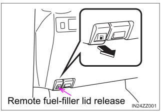
Refueling
Before refueling, close all the doors, windows, and the liftgate/trunk lid, and switch the ignition OFF.
To open the fuel-filler lid, pull the remote fuel-filler lid release.