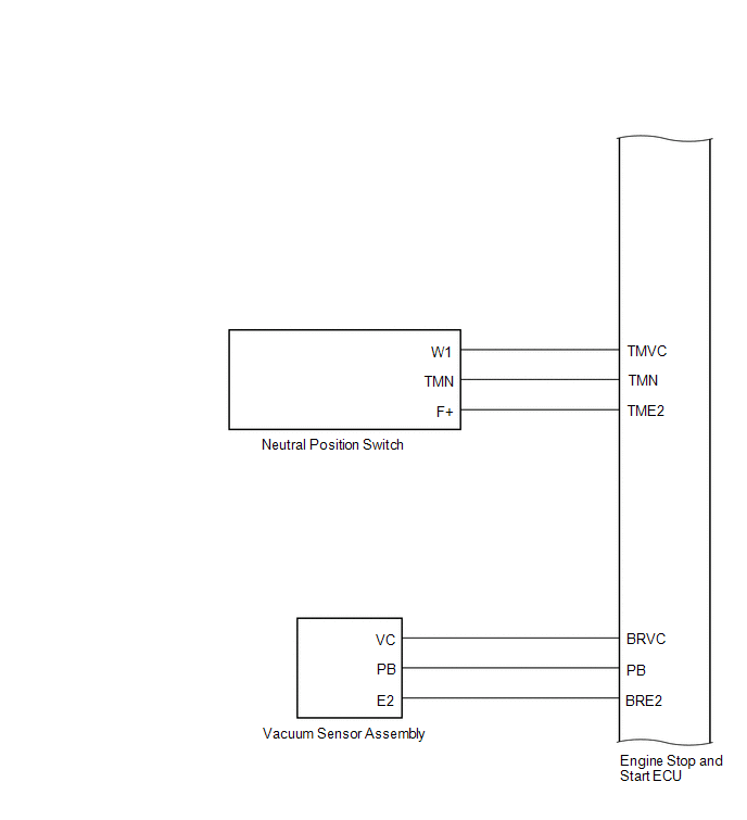
Toyota Yaris: Stop And Start System / System Diagram
SYSTEM DIAGRAM


 Parts Location
PARTS LOCATION ILLUSTRATION
*A w/ Toyota Safety Sense *B w/ Active Noise Control System *1 ENGINE HOOD COURTESY SWITCH (HOOD LOCK ASSEMBLY) *2 VACUUM SENSOR ASSEMBLY *3 INNER REAR VIEW MIRROR ASSEMBLY *4 ECM *5 SKID CONTROL ECU (BRAKE ACTUATOR ASSEMBLY) *6 EXTERNAL BACKUP BOOST CONVERTER (ECO RUN VEHICLE CONVERTER ASSEMBLY) *7 MILLIMETER WAVE RADAR SENSOR ASSEMBLY *8 FORWARD RECOGNITION CAMERA *9 ENGINE ROOM RELAY BLOCK - EFI-MAIN NO...
 System Description
SYSTEM DESCRIPTION STOP AND START CONTROL The stop and start system operates according to the following conditions, achieving appropriate engine stop and start control together with safe and smooth driving characteristics...
Other information:
Toyota Yaris XP210 (2020-2024) Reapir and Service Manual: Disassembly
DISASSEMBLY CAUTION / NOTICE / HINT NOTICE: Before installation of each part, thoroughly clean and dry it. Then apply grease or oil as necessary. Do not use alkaline chemicals to clean aluminum parts, rubber parts or precoated bolts. Also, do not use non-residue solvent or other cleaning oils to clean O-rings, oil seals or rubber parts...
Toyota Yaris XP210 (2020-2024) Reapir and Service Manual: Disassembly
DISASSEMBLY PROCEDURE 1. REMOVE CYLINDER BOOT (a) Using a screwdriver with its tip wrapped with protective tape, remove the 4 cylinder boots from the front disc brake cylinder. NOTICE: Do not forcefully pry off the retainer. Be careful not to damage the front disc brake cylinder...
Categories
- Manuals Home
- Toyota Yaris Owners Manual
- Toyota Yaris Service Manual
- Brake System Control Module "A" System Voltage System Voltage Low (C137BA2)
- To Set Speed
- Headlights
- New on site
- Most important about car
Key Suspend Function
If a key is left in the vehicle, the functions of the key left in the vehicle are temporarily suspended to prevent theft of the vehicle.
To restore the functions, press the unlock button on the functions-suspended key in the vehicle.
Copyright © 2024 www.toyaris4.com