Toyota Yaris: Millimeter Wave Radar Sensor / Removal
REMOVAL
CAUTION / NOTICE / HINT
The necessary procedures (adjustment, calibration, initialization, or registration) that must be performed after parts are replaced during millimeter wave radar sensor assembly removal/installation are shown below.
Necessary Procedure After Parts Removed/Installed/Replaced| Replaced Part or Performed Procedure | Necessary Procedure | Effect/Inoperative Function when Necessary Procedure not Performed | Link |
|---|---|---|---|
| Millimeter wave radar sensor assembly | Adjust millimeter wave radar sensor assembly |
| Triangle Target:
Flat Surface Target:
Driving Adjustment:
|
| Update ECU security key | Vehicle control history (RoB) are stored |
|


PROCEDURE
1. REMOVE FRONT BUMPER ASSEMBLY
Click here

2. REMOVE MILLIMETER WAVE RADAR SENSOR ASSEMBLY
| (a) Disconnect the connector. |
|

(b) Remove the 2 bolts and screw.

 | Bolt |
 | Screw |
(c) Disengage the guides to remove the millimeter wave radar sensor assembly.
NOTICE:
Do not reuse the millimeter wave radar sensor assembly if it has been dropped or subjected to a severe impact.
 Components
C..
 Installation
INSTALLATION PROCEDURE 1. INSTALL MILLIMETER WAVE RADAR SENSOR ASSEMBLY NOTICE: If the millimeter wave radar sensor assembly has been struck or dropped, replace the millimeter wave radar sensor assembly with a new one...
Other information:
Toyota Yaris XP210 (2020-2024) Reapir and Service Manual: Fail-safe Chart
FAIL-SAFE CHART If any of the following DTCs are stored, the engine stop and start ECU enters fail-safe mode to preserve vehicle operability. DTC Component Fail-safe Operation Fail-safe Deactivation Condition P033562 Open in engine speed signal circuit Stop and start control is prohibited Engine is automatically restarted if a DTC is stored while the engine is stopped by stop and start control All of the following conditions are met for 10 seconds: Normal communication with ECM Engine speed 500 rpm or higher Engine speed (communication signal) 500 rpm or higher Difference between engine speed from pulse signal and engine speed from communication signal is less than 100 rpm P055500 P05552A Vacuum sensor assembly Brake booster assembly Vacuum hose (brake booster hose) Stop and start control is prohibited Engine is automatically restarted if a DTC is stored while the engine is stopped by stop and start control One of the following conditions is met: Vacuum changes while the brake pedal is depressed Vacuum changes a specified number of times while the vehicle is being driven faster than a certain vehicle speed P055511 P055515 Vacuum sensor assembly circuit Stop and start control is prohibited Engine is automatically restarted if a DTC is stored while the engine is stopped by stop and start control Sensor output is within standard range P060629 Engine stop and start ECU Stop and start control is prohibited Engine is automatically restarted if a DTC is stored while the engine is stopped by stop and start control Pass condition detected and ignition switch turned to ON P060B1C P060B49 P060B71 Analog to digital converter (Engine stop and start ECU) Stop and start control is prohibited Engine is automatically restarted if a DTC is stored while the engine is stopped by stop and start control Pass condition detected and ignition switch turned to ON P061519 ST NO...
Toyota Yaris XP210 (2020-2024) Reapir and Service Manual: Transmitter Battery
ComponentsCOMPONENTS ILLUSTRATION *1 MECHANICAL KEY *2 TRANSMITTER BATTERY *3 TRANSMITTER HOUSING CASE *4 TRANSMITTER HOUSING COVER RemovalREMOVAL CAUTION / NOTICE / HINT NOTICE: Take extra care when handling these precision electronic components...
Categories
- Manuals Home
- Toyota Yaris Owners Manual
- Toyota Yaris Service Manual
- Auto Lock/Unlock Function
- Opening and Closing the Liftgate/Trunk Lid
- Speedometer, Odometer, Trip Meter and Trip Meter Selector
- New on site
- Most important about car
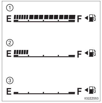
Fuel Gauge
The fuel gauge shows approximately how much fuel is remaining in the tank when the ignition is switched ON. We recommend keeping the tank over 1/4 full.