Toyota Yaris: Camshaft / Removal
REMOVAL
CAUTION / NOTICE / HINT
The necessary procedures (adjustment, calibration, initialization, or registration) that must be performed after parts are removed and installed, or replaced during camshaft removal/installation are shown below.
Necessary Procedure After Parts Removed/Installed/Replaced| Replaced Part or Performed Procedure | Necessary Procedure | Effect/Inoperative Function when Necessary Procedure not Performed | Link |
|---|---|---|---|
| Inspection After Repair |
|
|

NOTICE:
This procedure includes the removal of small-head bolts. Refer to Small-Head Bolts of Basic Repair Hint to identify the small-head bolts.
Click here

HINT:
When the cable is disconnected / reconnected to the auxiliary battery terminal, systems temporarily stop operating. However, each system has a function that completes learning the first time the system is used.
-
Learning completes when vehicle is driven
Effect/Inoperative Function When Necessary Procedures are not Performed
Necessary Procedures
Link
Lane tracing assist system
Drive the vehicle straight ahead at 35 km/h (22 mph) or more for 5 second or more.

Pre-collision system
Parking support brake system
Stop and start system
Drive the vehicle until stop and start control is permitted (approximately 5 to 60 minutes)

-
Learning completes when vehicle is operated normally
Effect/Inoperative Function When Necessary Procedures are not Performed
Necessary Procedures
Link
Power door lock control system
- Back door opener
Perform door unlock operation with door control switch or electrical key transmitter sub-assembly switch.

Air conditioning system
After the ignition switch is turned to ON, the servo motor standard position is recognized.
-
PROCEDURE
1. REMOVE ENGINE ASSEMBLY
Click here

2. REMOVE TIMING GEAR COVER INSULATOR
Click here

3. REMOVE SPARK PLUG
Click here

4. REMOVE OIL PRESSURE AND TEMPERATURE SENSOR
Click here

5. REMOVE CAMSHAFT POSITION SENSOR (for Intake Side)
Click here

6. REMOVE CAMSHAFT POSITION SENSOR (for Exhaust Side)
Click here

7. REMOVE CAM TIMING OIL CONTROL SOLENOID ASSEMBLY (for Intake Side)
Click here

8. REMOVE CAM TIMING OIL CONTROL SOLENOID ASSEMBLY (for Exhaust Side)
Click here

9. REMOVE WATER INLET WITH THERMOSTAT SUB-ASSEMBLY
Click here

10. REMOVE WATER INLET WITH WATER PUMP HOUSING SUB-ASSEMBLY
Click here

11. REMOVE OIL FILLER CAP ASSEMBLY
Click here

12. REMOVE CRANKSHAFT POSITION SENSOR
Click here

13. REMOVE PCV VALVE (VENTILATION VALVE SUB-ASSEMBLY)
Click here

14. REMOVE VACUUM PUMP ASSEMBLY
Click here

15. REMOVE CRANKSHAFT PULLEY ASSEMBLY
Click here

16. REMOVE CYLINDER HEAD COVER SUB-ASSEMBLY
Click here

17. REMOVE SPARK PLUG TUBE GASKET
Click here

18. REMOVE NO. 1 VACUUM PUMP BRACKET
Click here

19. REMOVE ENGINE MOUNTING BRACKET RH
Click here

20. REMOVE NO. 2 TIMING CHAIN COVER ASSEMBLY
Click here

21. REMOVE TIMING CHAIN COVER OIL SEAL
Click here

22. REMOVE TIMING CHAIN COVER ASSEMBLY
Click here

23. SET NO. 1 CYLINDER TO TDC (COMPRESSION)
Click here

24. REMOVE NO. 1 CHAIN TENSIONER ASSEMBLY
Click here

25. REMOVE TIMING CHAIN GUIDE
Click here

26. REMOVE DAMPER PLATE SPACER
Click here

27. REMOVE CHAIN TENSIONER SLIPPER
Click here

28. REMOVE CHAIN SUB-ASSEMBLY
Click here

29. REMOVE NO. 1 CHAIN VIBRATION DAMPER
Click here

30. REMOVE CRANKSHAFT TIMING GEAR OR SPROCKET
Click here

31. REMOVE CAMSHAFT TIMING EXHAUST GEAR ASSEMBLY
Click here

32. REMOVE CAMSHAFT TIMING GEAR ASSEMBLY
Click here

33. REMOVE FUEL PUMP LIFTER GUIDE
Click here

34. REMOVE FUEL PUMP LIFTER HOUSING
Click here

35. REMOVE CAMSHAFT POSITION SENSOR HOLDER
Click here

36. REMOVE CAMSHAFT BEARING CAP
Click here

37. REMOVE EXHAUST CAMSHAFT SUB-ASSEMBLY
Click here

38. REMOVE INTAKE CAMSHAFT SUB-ASSEMBLY
Click here

 Components
COMPONENTS ILLUSTRATION
*1 SPARK PLUG *2 OIL PRESSURE AND TEMPERATURE SENSOR *3 CAMSHAFT POSITION SENSOR (for Intake Side) *4 CAMSHAFT POSITION SENSOR (for Exhaust Side) *5 CAM TIMING OIL CONTROL SOLENOID ASSEMBLY (for Intake Side) *6 CAM TIMING OIL CONTROL SOLENOID ASSEMBLY (for Exhaust Side) *7 WATER INLET WITH THERMOSTAT SUB-ASSEMBLY *8 WATER INLET WITH WATER PUMP HOUSING SUB-ASSEMBLY *9 OIL FILLER CAP ASSEMBLY *10 O-RING *11 CRANKSHAFT POSITION SENSOR *12 PCV VALVE (VENTILATION VALVE SUB-ASSEMBLY) *13 VACUUM PUMP ASSEMBLY *14 GASKET *15 NO...
 Installation
INSTALLATION CAUTION / NOTICE / HINT NOTICE: This procedure includes the installation of small-head bolts. Refer to Small-Head Bolts of Basic Repair Hint to identify the small-head bolts...
Other information:
Toyota Yaris XP210 (2020-2024) Reapir and Service Manual: Reassembly
REASSEMBLY PROCEDURE 1. INSTALL STARTER CENTER BEARING CLUTCH SUB-ASSEMBLY (a) Apply high-temperature grease to the pinion drive lever as shown in the illustration. *1 Starter Center Bearing Clutch Sub-assembly *2 Starter Drive Housing Assembly *3 Pinion Drive Lever *4 Rubber Seal High-temperature Grease (b) Install the pinion drive lever and rubber seal to the starter center bearing clutch sub-assembly...
Toyota Yaris XP210 (2020-2024) Reapir and Service Manual: Check Mode Procedure
CHECK MODE PROCEDURE CHECK MODE: DTC CHECK (a) Select "Check Mode" and proceed with checking using the GTS. Body Electrical > SRS Airbag > Utility Tester Display Check Mode NOTICE: Select Check Mode on the GTS to clear the DTCs (both current and history)...
Categories
- Manuals Home
- Toyota Yaris Owners Manual
- Toyota Yaris Service Manual
- Fuse Panel Description
- How to use USB mode
- Key Battery Replacement
- New on site
- Most important about car
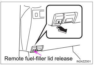
Refueling
Before refueling, close all the doors, windows, and the liftgate/trunk lid, and switch the ignition OFF.
To open the fuel-filler lid, pull the remote fuel-filler lid release.