Toyota Yaris: G16e-gts (emission Control) / Purge Valve
Components
COMPONENTS
ILLUSTRATION

| *1 | FUEL VAPOR FEED HOSE ASSEMBLY | *2 | NO. 1 FUEL VAPOR FEED HOSE |
| *3 | PURGE VALVE (PURGE VSV) | *4 | NO. 1 ENGINE COVER SUB-ASSEMBLY |
 | N*m (kgf*cm, ft.*lbf): Specified torque | - | - |
Removal
REMOVAL
PROCEDURE
1. REMOVE NO. 1 ENGINE COVER SUB-ASSEMBLY
Click here

2. REMOVE PURGE VALVE (PURGE VSV)
| (a) Disconnect the purge valve (purge VSV) connector. |
|

| (b) Disconnect the fuel vapor feed hose assembly from the purge valve (purge VSV). |
|

| (c) Disconnect the No. 1 fuel vapor feed hose from the purge valve (purge VSV). |
|

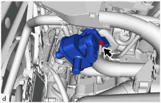
| (d) Remove the nut and purge valve (purge VSV) from the intake manifold. |
|
Inspection
INSPECTION
PROCEDURE
1. INSPECT PURGE VALVE (PURGE VSV)
(a) Measure the resistance according to the value(s) in the table below.
Standard Resistance:
| Tester Connection | Condition | Specified Condition |
|---|---|---|
| D96-1 - D96-2 | 20°C (68°F) | 23 to 26 Ω |
If the result is not as specified, replace the purge valve (purge VSV).
| (b) Apply auxiliary battery voltage between the terminals of the purge valve (purge VSV) and check that the following occurs when blowing air into the port (E). OK:
If the result is not as specified, replace the purge valve (purge VSV). |
|

Installation
INSTALLATION
PROCEDURE
1. INSTALL PURGE VALVE (PURGE VSV)
(a) Install the purge valve (purge VSV) to the intake manifold with the nut.
Torque:
10 N·m {102 kgf·cm, 7 ft·lbf}
(b) Connect the No. 1 fuel vapor feed hose to the purge valve (purge VSV).
(c) Connect the fuel vapor feed hose assembly to the purge valve (purge VSV).
(d) Connect the purge valve (purge VSV) connector.
2. INSTALL NO. 1 ENGINE COVER SUB-ASSEMBLY
Click here

 Pcv Valve
ComponentsCOMPONENTS ILLUSTRATION
*1 PCV VALVE (VENTILATION VALVE SUB-ASSEMBLY) - - On-vehicle InspectionON-VEHICLE INSPECTION PROCEDURE 1...
 Vacuum Regulating Valve
ComponentsCOMPONENTS ILLUSTRATION
*1 VACUUM REGULATING VALVE ASSEMBLY *2 NO. 2 VACUUM TRANSMITTING HOSE *3 NO. 1 VACUUM TRANSMITTING HOSE *4 NO...
Other information:
Toyota Yaris XP210 (2020-2024) Reapir and Service Manual: Starter Signal Circuit
DESCRIPTION While the engine is being cranked, current flows from terminal STAR of the certification ECU (smart key ECU assembly) to the clutch start switch assembly and to terminal STA of the ECM (STA signal). WIRING DIAGRAM Refer to DTC P061512. Click here CAUTION / NOTICE / HINT NOTICE: Inspect the fuses for circuits related to this system before performing the following procedure...
Toyota Yaris XP210 (2020-2024) Reapir and Service Manual: Removal
REMOVAL CAUTION / NOTICE / HINT The necessary procedures (adjustment, calibration, initialization, or registration) that must be performed after parts are removed, installed, or replaced during brake pedal support assembly removal/installation are shown below...
Categories
- Manuals Home
- Toyota Yaris Owners Manual
- Toyota Yaris Service Manual
- Headlights
- Removal
- Starting the Engine
- New on site
- Most important about car
Fuel-Filler Lid and Cap
WARNING
When removing the fuel-filler cap, loosen the cap slightly and wait for any hissing to stop, then remove it
Fuel spray is dangerous. Fuel can burn skin and eyes and cause illness if ingested. Fuel spray is released when there is pressure in the fuel tank and the fuel-filler cap is removed too quickly.