Toyota Yaris: Air Conditioning System / Problem Symptoms Table
PROBLEM SYMPTOMS TABLE
NOTICE:
- Use the table below to help determine the cause of problem symptoms. If multiple suspected areas are listed, the potential causes of the symptoms are listed in order of probability in the "Suspected Area" column of the table. Check each symptom by checking the suspected areas in the order they are listed. Replace parts as necessary.
- Inspect the fuses and relays related to this system before inspecting the suspected areas below.
-
The air conditioning system uses the CAN communication system. First, confirm that there is no malfunction in the CAN communication system. Refer to the How to Proceed with Troubleshooting procedure.
Click here

- Perform the inspection when the vehicle is at ambient temperature. If this is not done, there could be a risk of injury depending on the location being inspected.
VEHICLE CHECK ITEMS
HINT:
- You can reduce the number of systems to check by using the results of the following operation check.
- Perform the following checks based on Customer Feedback and the vehicle condition.
- The customer's opinion may not be consistent with the actual problem (eg: the cooling performance of the air conditioner is bad → actually, the wind volume is weak). It is important to check the problem symptoms accurately and judge correctly based on various sources of information.
- Judgment as to whether the air conditioner panel is normal or abnormal can be judged by checking if the indicator illuminates or turns off when the switch is operated.
- During servo motor initialization, the AUTO indicator light comes on, and then goes off when initialization has finished.
- If the performance of the air conditioner is poor or there is a foul odor, check for clogging in the clean air filter.
Malfunction Operation/Function:
| Common Function of Cool and Heater Function | Only Cool Air Function | Only Heater Function | Suspected Area | |||
|---|---|---|---|---|---|---|
| A/C Switch Operation | Blower Operation | Recirculation/Fresh Function | Air Outlet Changing Function | |||
| x | o | o | o | x | x | Go to "Problem Symptoms Table: Air Conditioning Control" |
| o | o | o | o | x | o | Go to "Problem Symptoms Table: Cooling Function" |
| o | o | o | o | o | x | Go to "Problem Symptoms Table: Heater Function" |
| o | x | o | o | x | x | Go to "Problem Symptoms Table: Blower Control" |
| o | o | x | o | x | x | Go to "Problem Symptoms Table: Air Inlet Control" |
| o | o | o | x | x | x | Go to "Problem Symptoms Table: Air Outlet Control" |
| x | x | x | x | x | x | Air Conditioning Amplifier Assembly or Air Conditioning Assembly is Defective |
AIR CONDITIONING CONTROL
| Symptom | Suspected Area | Link |
|---|---|---|
| Air conditioning system cannot be operated using air conditioning control assembly
|
|
|
| Air conditioning system cannot be operated using air conditioning control assembly
| Air conditioning control assembly |
|
| Air conditioning system cannot be operated using air conditioning control assembly immediately after starting the engine
| Refer to "INITIALIZATION" |
|
| A/C switch indicator does not illuminate |
|
|


COOLING FUNCTION
| Symptom | Suspected Area | Link |
|---|---|---|
| No cool air comes out
|
|
|
|
|
|
| Temperature of outlet air is cooler on left or right side
|
|
|


HEATER FUNCTION
| Symptom | Suspected Area | Link |
|---|---|---|
|
|
|
| Temperature of outlet air is warmer on left or right side
|
|
|


BLOWER CONTROL
| Symptom | Suspected Area | Link |
|---|---|---|
| Blower motor does not operate at all
|
|
|
| Airflow volume cannot be changed |
|
|
|
|
|


AIR INLET CONTROL
| Symptom | Suspected Area | Link |
|---|---|---|
|
|
|
|
|
|


AIR OUTLET CONTROL
| Symptom | Suspected Area | Link |
|---|---|---|
| Air outlet mode cannot be changed
|
|
|
| Air outlet mode cannot be changed
| Air conditioning control assembly |
|


DEFROSTER CONTROL
| Symptom | Suspected Area | Link |
|---|---|---|
| Windshield frequently fogs up |
|
|

 Utility
UTILITY REFRIGERANT SHORTAGE CHECK USING GTS (a) Check that the following conditions are met and perform the refrigerant shortage check according to the display on the GTS...
 Terminals Of Ecu
TERMINALS OF ECU
CHECK AIR CONDITIONING AMPLIFIER ASSEMBLY (a) Check air conditioning amplifier assembly. (1) Disconnect the H24 air conditioning amplifier assembly connector...
Other information:
Toyota Yaris XP210 (2020-2024) Reapir and Service Manual: License Plate Light Bulb
C..
Toyota Yaris XP210 (2020-2024) Reapir and Service Manual: Brake Pressure Sensor "A" Circuit Voltage Above Threshold (C054017)
DESCRIPTION DTC No. Detection Item DTC Detection Condition Trouble Area DTC Output from C054017 Brake Pressure Sensor "A" Circuit Voltage Above Threshold When vehicle speed exceeds 3 km/h (2 mph) and stop light switch assembly is OFF, master cylinder pressure continuously exceeds 1...
Categories
- Manuals Home
- Toyota Yaris Owners Manual
- Toyota Yaris Service Manual
- Headlights
- How to use USB mode
- Auto Lock/Unlock Function
- New on site
- Most important about car
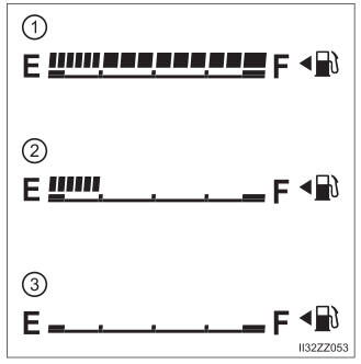
Fuel Gauge
The fuel gauge shows approximately how much fuel is remaining in the tank when the ignition is switched ON. We recommend keeping the tank over 1/4 full.