Toyota Yaris: Lighting (int) / Personal Light
Components
COMPONENTS
ILLUSTRATION

| *1 | MAP LIGHT ASSEMBLY | - | - |
Removal
REMOVAL
PROCEDURE
1. REMOVE MAP LIGHT ASSEMBLY
(a) Using a moulding remover D, disengage the clips to remove the map light assembly as shown in the illustration.

 | Remove in this Direction |
| (b) Disconnect the connector. |
|

Inspection
INSPECTION
PROCEDURE
1. INSPECT MAP LIGHT ASSEMBLY
(a) Check the map light.
| (1) Apply auxiliary battery voltage to the map light assembly and check that the map light comes on. OK:
If the result is not as specified, replace the map light assembly. |
|

(b) Check the door switch.
| (1) Measure the resistance according to the value(s) in the table below. Standard Resistance:
If the result is not as specified, replace the map light assembly. |
|

Installation
INSTALLATION
PROCEDURE
1. INSTALL MAP LIGHT ASSEMBLY
(a) Connect the connector.
(b) Engage the clips to install the map light assembly as shown in the illustration.

 | Install in this Direction |
 Door Unlock Detection Switch Circuit
DESCRIPTION The main body ECU (multiplex network body ECU) detects the condition of each door unlock detection switch. WIRING DIAGRAM
CAUTION / NOTICE / HINT NOTICE: Before replacing the main body ECU (multiplex network body ECU), refer to Registration...
 Room Light
ComponentsCOMPONENTS ILLUSTRATION
*1 NO. 1 ROOM LIGHT ASSEMBLY *2 NO. 1 ROOM LIGHT BULB *3 NO. 1 ROOM LIGHT LENS *4 NO. 1 ROOM LIGHT HOUSING RemovalREMOVAL PROCEDURE 1...
Other information:
Toyota Yaris XP210 (2020-2024) Reapir and Service Manual: Analog to Digital Converter Circuit Voltage Out of Range (P060B1C,P060B49,P060B71)
DESCRIPTION If an internal malfunction occurs in the engine stop and start ECU, it stores P060B1C, P060B49 or P060B71 and blinks the stop and start cancel indicator. DTC No. Detection Item DTC Detection Condition Trouble Area Warning Indicate Memory Note P060B1C Analog to Digital Converter Circuit Voltage Out of Range Both of the following conditions are met for 0...
Toyota Yaris XP210 (2020-2024) Reapir and Service Manual: Lack of Power (Turbocharger System)
CAUTION / NOTICE / HINT HINT: The diagnosis flowchart is for lack of power due to turbocharger factors. If symptom-specific diagnosis indicates a turbocharger related problem, check using this flowchart. PROCEDURE 1. CHECK TURBOCHARGER SUB-ASSEMBLY (a) Check for oil leaks and large carbon deposits around the connecting surfaces of the turbocharger sub-assembly...
Categories
- Manuals Home
- Toyota Yaris Owners Manual
- Toyota Yaris Service Manual
- Key Battery Replacement
- Auto Lock/Unlock Function
- Low Engine Coolant Temperature Indicator Light (Blue)
- New on site
- Most important about car
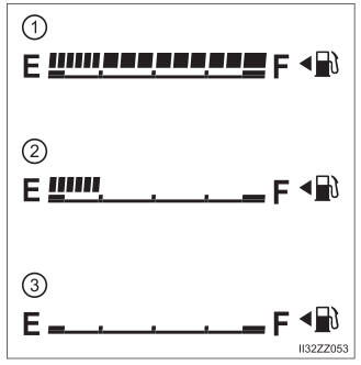
Fuel Gauge
The fuel gauge shows approximately how much fuel is remaining in the tank when the ignition is switched ON. We recommend keeping the tank over 1/4 full.