Toyota Yaris: Spiral Cable / Installation
INSTALLATION
PROCEDURE
1. INSPECT SPIRAL CABLE WITH SENSOR SUB-ASSEMBLY
(a) Check that the spiral cable with sensor sub-assembly is center position.
OK:
The connector is at the top.
The matchmarks are aligned.
The colored roller or the top of the flat cable U-turn can be checked from the check window.

| *A | w/ Heated Steering Wheel System | *B | w/o Heated Steering Wheel System |
| *a | Check Window | *b | Top of Flat Cable U-turn |
| *c | Matchmark | - | - |
(b) If the spiral cable with sensor sub-assembly is not centered, center it.
NOTICE:
Failure to observe the following precautions may result in damage to the spiral cable with sensor sub-assembly.
- When rotating the spiral cable with sensor sub-assembly, make sure to push on the interlock to release the interlock.
- Do not turn the spiral cable with sensor sub-assembly using the airbag wire harness.
- Do not forcibly rotate the part.

| *a | Interlock |
 | Counterclockwise |
(1) While pushing on the interlock indicated in the illustration. Make sure to rotate the spiral cable with sensor sub-assembly counterclockwise slowly by hand until it stops.
NOTICE:
Make sure to rotate the spiral cable with sensor sub-assembly counterclockwise. If rotated clockwise, it may be damaged or centering may no longer be possible.
HINT:
The interlock operates at the top and bottom of the connector.
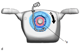
| (2) If the spiral cable with sensor sub-assembly stops rotating and the connector has moved past the bottom, return the connector to the bottom as shown in the illustration. |
|


| *a | Interlock |
 | Clockwise |
(3) While pushing on the interlock, rotate the spiral cable with sensor sub-assembly clockwise approximately 2.5 times to move the connector from the bottom to the top.
NOTICE:
If the connector is rotated clockwise from the bottom 5 times or more, the spiral cable with sensor sub-assembly may be damaged.
HINT:
The interlock operates at the top and bottom of the connector.
(4) Check that the spiral cable with sensor sub-assembly is center position.
OK:
The connector is at the top.
The matchmarks are aligned.
The colored roller or the top of the flat cable U-turn can be checked from the check window.

| *A | w/ Heated Steering Wheel System | *B | w/o Heated Steering Wheel System |
| *a | Check Window | *b | Top of Flat Cable U-turn |
| *c | Matchmark | - | - |
NOTICE:
If the spiral cable with sensor sub-assembly cannot be centered, it is possible that the spiral cable sub-assembly is broken. Replace the spiral cable sub-assembly with a new one.
2. INSTALL STEERING SENSOR
| (a) Align the guides and engage the claws to install the steering sensor to the spiral cable sub-assembly. NOTICE:
|
|

(b) Remove the lock pin from the steering sensor.
3. PLACE FRONT WHEELS FACING STRAIGHT AHEAD

4. INSTALL SPIRAL CABLE WITH SENSOR SUB-ASSEMBLY
NOTICE:
- Do not replace the spiral cable with sensor sub-assembly with the auxiliary battery connected and the ignition switch on (IG).
- Do not rotate the spiral cable with sensor sub-assembly with the auxiliary battery connected and the ignition switch on (IG).
- When rotating the spiral cable with sensor sub-assembly to check the operation of the spiral cable with sensor sub-assembly (checking for abnormal noise, checking the DTC, Data list, etc.) make sure to perform the inspection with the steering wheel assembly installed.
(a) Check that the ignition switch is off.
(b) Check that the cable is disconnected from the negative (-) auxiliary battery terminal.
CAUTION:
- Wait at least 90 seconds after disconnecting the cable from the negative (-) auxiliary battery terminal to disable the SRS system.
- If the airbag deploys for any reason, it may cause a serious accident.
(c) Check that the front wheels are facing straight ahead.
(d) Set the turn signal switch to the neutral position.
NOTICE:
If it is not in the neutral position, the turn signal switch cancel ratchet may snap.
| (e) Engage the claw and clips to install the spiral cable with sensor sub-assembly. |
|

(f) Connect each connector.
NOTICE:
When connecting any airbag connector, take care not to damage the airbag wire harness.
HINT:
Refer to How to Connect or Disconnect Airbag Connector: Click here

5. INSTALL UPPER STEERING COLUMN COVER
Click here

6. INSTALL LOWER STEERING COLUMN COVER
Click here

7. ADJUST SPIRAL CABLE WITH SENSOR SUB-ASSEMBLY
(a) Check that the ignition switch is off.
(b) Check that the cable is disconnected from the negative (-) auxiliary battery terminal.
CAUTION:
- Wait at least 90 seconds after disconnecting the cable from the negative (-) auxiliary battery terminal to disable the SRS system.
- If the airbag deploys for any reason, it may cause a serious accident.
(c) Check that the spiral cable with sensor sub-assembly is center position.
OK:
The connector is at the top.
The colored roller or the top of the flat cable U-turn can be checked from the check window.

| *A | w/ Heated Steering Wheel System | *B | w/o Heated Steering Wheel System |
| *a | Check Window | *b | Top of Flat Cable U-turn |
(d) If the spiral cable with sensor sub-assembly is not centered, center it.
NOTICE:
Failure to observe the following precautions may result in damage to the spiral cable with sensor sub-assembly.
- When rotating the spiral cable with sensor sub-assembly, make sure to push on the interlock to release the interlock.
- Do not turn the spiral cable with sensor sub-assembly using the airbag wire harness.
- Do not forcibly rotate the part.

| *a | Interlock |
 | Counterclockwise |
(1) While pushing on the interlock indicated in the illustration. Make sure to rotate the spiral cable with sensor sub-assembly counterclockwise slowly by hand until it stops.
NOTICE:
If the connector is rotated clockwise from the bottom 5 times or more, the spiral cable with sensor sub-assembly may be damaged.
HINT:
The interlock operates at the top and bottom of the connector.
| (2) If the spiral cable with sensor sub-assembly stops rotating and the connector has moved past the bottom, return the connector to the bottom as shown in the illustration. |
|

| *a | Interlock |
 | Clockwise |
(3) While pushing on the interlock, rotate the spiral cable with sensor sub-assembly clockwise approximately 2.5 times to move the connector from the bottom to the top.
NOTICE:
If the connector is rotated clockwise from the bottom 5 times or more, the spiral cable with sensor sub-assembly may be damaged.
HINT:
The interlock operates at the top and bottom of the connector.
(4) Check that the spiral cable with sensor sub-assembly is center position.
OK:
The connector is at the top.
The colored roller or the top of the flat cable U-turn can be checked from the check window.

| *A | w/ Heated Steering Wheel System | *B | w/o Heated Steering Wheel System |
| *a | Check Window | *b | Top of Flat Cable U-turn |
NOTICE:
If the spiral cable sub-assembly cannot be centered, it is possible that the spiral cable sub-assembly is broken. Replace the spiral cable sub-assembly with a new one.
8. INSTALL STEERING WHEEL ASSEMBLY
Click here

9. INSTALL HORN BUTTON ASSEMBLY
Click here

10. PERFORM DIAGNOSTIC SYSTEM CHECK
Click here

11. CHECK SRS WARNING LIGHT
Click here

12. PERFORM SYSTEM CALIBRATION (When Removing or Replacing the steering sensor)
Click here

13. PERFORM CALIBRATION
Click here

 Inspection
INSPECTION PROCEDURE 1. INSPECT SPIRAL CABLE SUB-ASSEMBLY NOTICE:
Do not remove the steering sensor from the spiral cable sub-assembly when inspecting the spiral cable sub-assembly...
 Steering Pad
..
Other information:
Toyota Yaris XP210 (2020-2024) Reapir and Service Manual: Engine Coolant Temperature Receiver Gauge Malfunction
DESCRIPTION In this circuit, the combination meter assembly receives engine coolant temperature signals from the ECM via CAN communication. The combination meter assembly displays an engine coolant temperature warning based on the data received from the ECM...
Toyota Yaris XP210 (2020-2024) Reapir and Service Manual: Installation
INSTALLATION PROCEDURE 1. INSPECT COMPRESSOR OIL (a) Remove the suction seal cap. (b) Using a screwdriver with its tip wrapped in protective tape, insert the screwdriver through the suction port and set the VST valve (valve inside suction port) to the open position...
Categories
- Manuals Home
- Toyota Yaris Owners Manual
- Toyota Yaris Service Manual
- To Set Speed
- How to use USB mode
- Fuse Panel Description
- New on site
- Most important about car
Break-In Period
No special break-in is necessary, but a few precautions in the first 600 miles (1,000 km) may add to the performance, economy, and life of the vehicle.
Do not race the engine. Do not maintain one constant speed, either slow or fast, for a long period of time. Do not drive constantly at full-throttle or high engine rpm for extended periods of time. Avoid unnecessary hard stops. Avoid full-throttle starts.