Toyota Yaris: Sfi System / Fuel Rail Pressure Sensor (Low) Circuit Short to Ground (P107A11)
DESCRIPTION

The No. 2 fuel pressure sensor (for low pressure side) replaces the fuel pressure with electrical signals and outputs them to the ECM. The ECM controls the optimal fuel pressure for the operation conditions to reduce the fuel pump power consumption and improve fuel economy.
| DTC No. | Detection Item | DTC Detection Condition | Trouble Area | MIL | Note |
|---|---|---|---|---|---|
| P107A11 | Fuel Rail Pressure Sensor (Low) Circuit Short to Ground | The No. 2 fuel pressure sensor (for low pressure side) output voltage is less than 0.43 V for 3 seconds or more (1 trip detection logic). |
| Comes on | SAE: P107C |
HINT:
When a DTC is output, check the Data List item "Fuel Pressure (Low) / Fuel Pressure 2" using the GTS.
Click here

| DTC No. | Fuel Pressure (Low) / Fuel Pressure 2 | Malfunction |
|---|---|---|
| P107A11 | Approximately 0 kPag |
|
If the Data List displays a normal value, the normal value may be due to a temporary recovery from the malfunction condition. Check for intermittent problems.
MONITOR DESCRIPTION
This DTC is stored if the No. 2 fuel pressure sensor (for low pressure side) output voltage is out of the standard range due to an open or short in the sensor circuit.
MONITOR STRATEGY
| Required Sensors/Components (Main) | No. 2 fuel pressure sensor (for low pressure side) |
| Frequency of Operation | Continuous |
CONFIRMATION DRIVING PATTERN
- Connect the GTS to the DLC3.
- Turn the ignition switch to ON.
- Turn the GTS on.
- Clear the DTCs (even if no DTCs are stored, perform the clear DTC procedure).
- Turn the ignition switch off and wait for at least 30 seconds.
- Start the engine.
- Idle the engine for 10 seconds or more [A].
- Turn the GTS on.
- Enter the following menus: Powertrain / Engine / Trouble Codes [B].
-
Read the pending DTCs.
HINT:
- If a pending DTC is output, the system is malfunctioning.
- If a pending DTC is not output, perform the following procedure.
- Enter the following menus: Powertrain / Engine / Utility / All Readiness.
- Input the DTC: P107A11.
-
Check the DTC judgment result.
GTS Display
Description
NORMAL
- DTC judgment completed
- System normal
ABNORMAL
- DTC judgment completed
- System abnormal
INCOMPLETE
- DTC judgment not completed
- Perform driving pattern after confirming DTC enabling conditions
HINT:
- If the judgment result is NORMAL, the system is normal.
- If the judgment result is ABNORMAL, the system has a malfunction.
- If the judgment result is INCOMPLETE, perform steps [A] through [B] again.
WIRING DIAGRAM

CAUTION / NOTICE / HINT
HINT:
Read Freeze Frame Data using the GTS. The ECM records vehicle and driving condition information as Freeze Frame Data the moment a DTC is stored. When troubleshooting, Freeze Frame Data can help determine if the vehicle was moving or stationary, if the engine was warmed up or not, if the air fuel ratio was lean or rich, and other data from the time the malfunction occurred.
PROCEDURE
| 1. | CHECK HARNESS AND CONNECTOR |
HINT:
Make sure that the connector is properly connected. If it is not, securely connect it and check for DTCs again.
(a) Disconnect the No. 2 fuel pressure sensor (for low pressure side) connector.
(b) Turn the ignition switch to ON.
| (c) Measure the voltage according to the value(s) in the table below. Standard Voltage:
|
|

(d) Turn the ignition switch off and wait for at least 30 seconds.
(e) Measure the resistance according to the value(s) in the table below.
Standard Resistance:
| Tester Connection | Condition | Specified Condition |
|---|---|---|
| E4-1(VC) - E4-2(PFL) | Ignition switch off | 171 to 189 kΩ |
HINT:
Perform "Inspection After Repair" after replacing the No. 2 fuel pressure sensor (for low pressure side).
Click here

| OK |
 | REPLACE NO. 2 FUEL PRESSURE SENSOR (FOR LOW PRESSURE SIDE) |
|

| 2. | CHECK HARNESS AND CONNECTOR (NO. 2 FUEL PRESSURE SENSOR (FOR LOW PRESSURE SIDE) - ECM) |
(a) Disconnect the No. 2 fuel pressure sensor (for low pressure side) connector.
(b) Disconnect the ECM connector.
(c) Measure the resistance according to the value(s) in the table below.
Standard Resistance:
| Tester Connection | Condition | Specified Condition |
|---|---|---|
| E4-1(VC) - D104-120(VCPF) | Always | Below 1 Ω |
| E4-2(PFL) or D104-121(PFL) - Body ground and other terminals | Always | 10 kΩ or higher |
| OK |
 | REPLACE ECM |
| NG |
 | REPAIR OR REPLACE HARNESS OR CONNECTOR |
 Brake Switch "B" Circuit Short to Battery (P070312)
DESCRIPTION The stop light switch assembly is part of a duplex system that transmits two signals: STP and ST1-. These two signals are used by the ECM to monitor whether or not the brake system is working properly...
 Fuel Rail Pressure Sensor (Low) Circuit Short to Battery or Open (P107A15)
DESCRIPTION Refer to DTC P107A11. Click here
DTC No. Detection Item DTC Detection Condition Trouble Area MIL Note P107A15 Fuel Rail Pressure Sensor (Low) Circuit Short to Battery or Open The No...
Other information:
Toyota Yaris XP210 (2020-2024) Owner's Manual: Locking Lug Nuts (if equipped)
If your Toyota is equipped with the optional antitheft wheel lug nuts, a special key must be used to unlock the locking lug nut for each wheel. The key is stored in the glove compartment, center console storage, storage box, or trunk. Register the key and lug nuts with the lock manufacturer by filling out the registration card and mailing it in using the accompanying envelope...
Toyota Yaris XP210 (2020-2024) Reapir and Service Manual: On-vehicle Inspection
ON-VEHICLE INSPECTION PROCEDURE 1. INSPECT COOLER CONDENSER ASSEMBLY (a) If the cooler condenser assembly fins are dirty, clean them with water and dry them with compressed air. NOTICE: Do not damage the cooler condenser assembly fins. (b) If any cooler condenser assembly fins are bent, straighten them using a screwdriver or pliers...
Categories
- Manuals Home
- Toyota Yaris Owners Manual
- Toyota Yaris Service Manual
- Fuse Panel Description
- Battery Monitor Module General Electrical Failure (P058A01)
- Low Engine Coolant Temperature Indicator Light (Blue)
- New on site
- Most important about car
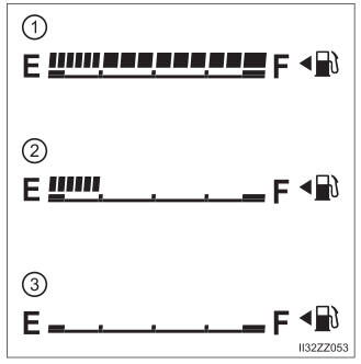
Fuel Gauge
The fuel gauge shows approximately how much fuel is remaining in the tank when the ignition is switched ON. We recommend keeping the tank over 1/4 full.