Toyota Yaris: Front Suspension / Front Lower Suspension Arm
Components
COMPONENTS
ILLUSTRATION

| *1 | NO.1 ENGINE UNDER COVER ASSEMBLY | *2 | FRONT LOWER NO. 1 SUSPENSION ARM SUB-ASSEMBLY |
| *3 | INNER NO. 1 ARM ATTACHMENT PLATE | - | - |
 | Tightening torque for "Major areas involving basic vehicle performance such as moving/turning/stopping" : N*m (kgf*cm, ft.*lbf) |
 | N*m (kgf*cm, ft.*lbf): Specified torque |
Removal
REMOVAL
CAUTION / NOTICE / HINT
The necessary procedures (adjustment, calibration, initialization, or registration) that must be performed after parts are removed, installed, or replaced during the front lower No. 1 suspension arm sub-assembly LH removal/installation are shown below.
Necessary Procedure After Parts Removed/Installed/Replaced| Replacement Part or Procedure | Necessary Procedure | Effect/Inoperative when not Performed | Link |
|---|---|---|---|
| Front wheel alignment adjustment | ECU Data Initialization | Active torque split AWD system |
|
| Calibration |
|
|


HINT:
- Use the same procedure for the RH side and LH side.
- The following procedure is for the LH side.
PROCEDURE
1. REMOVE FRONT WHEEL
Click here

2. REMOVE NO.1 ENGINE UNDER COVER ASSEMBLY
Click here

3. REMOVE FRONT LOWER NO. 1 SUSPENSION ARM SUB-ASSEMBLY
| (a) Remove the bolt, 2 nuts and separate the front lower No. 1 suspension arm sub-assembly from the front lower ball joint assembly. |
|

| (b) Remove inner No. 1 arm attachment plate from the front lower No. 1 suspension arm sub-assembly. |
|

| (c) Remove the 2 bolts, nut and front lower No. 1 suspension arm sub-assembly from the front suspension crossmember sub-assembly. NOTICE: Do not turn the nut. Loosen the bolt with the nut secured. |
|

Installation
INSTALLATION
CAUTION / NOTICE / HINT
HINT:
- Use the same procedure for the RH side and LH side.
- The following procedure is for the LH side.
PROCEDURE
1. TEMPORARILY INSTALL FRONT LOWER NO. 1 SUSPENSION ARM SUB-ASSEMBLY
(a) Temporarily install the front lower No. 1 suspension arm sub-assembly to the front suspension crossmember sub-assembly with the 2 bolts and nut.
(b) Connect the front lower No. 1 suspension arm sub-assembly and inner No. 1 arm attachment plate to the front lower ball joint assembly with the bolt and 2 nuts.
Torque:
89 N·m {908 kgf·cm, 66 ft·lbf}
2. INSTALL FRONT WHEEL
Click here

3. STABILIZE SUSPENSION
(a) Press down on the vehicle several times to stabilize the suspension.
4. FULLY TIGHTEN FRONT LOWER NO. 1 SUSPENSION ARM SUB-ASSEMBLY
| (a) Tighten the bolt (A). Torque: 147 N·m {1499 kgf·cm, 108 ft·lbf} |
|

(b) Fully tighten the bolt (B).
Torque:
125 N·m {1275 kgf·cm, 92 ft·lbf}
NOTICE:
Tighten the bolt with the nut secured.
5. INSTALL NO.1 ENGINE UNDER COVER ASSEMBLY
Click here

6. INSPECT AND ADJUST FRONT WHEEL ALIGNMENT
Click here

 Installation
INSTALLATION CAUTION / NOTICE / HINT HINT:
Use the same procedure for the RH side and LH side.
The following procedure is for the LH side.
PROCEDURE 1...

Other information:
Toyota Yaris XP210 (2020-2024) Reapir and Service Manual: Inspection
INSPECTION PROCEDURE 1. INSPECT FRONT DRIVE SHAFT ASSEMBLY (a) Check that there is no excessive play in the radial direction of the outboard joint. (b) Check that the inboard joint slides smoothly in the thrust direction. (c) Check that there is no excessive play in the radial direction of the inboard joint...
Toyota Yaris XP210 (2020-2024) Reapir and Service Manual: Interior Light Auto Cut Circuit
DESCRIPTION The main body ECU (multiplex network body ECU) controls operation of the DOME CUT relay in order to supply power to the interior lights. When the battery saving function operates while the interior lights are on, the main body ECU (multiplex network body ECU) opens the DOME CUT relay to turn off the lights...
Categories
- Manuals Home
- Toyota Yaris Owners Manual
- Toyota Yaris Service Manual
- Removal
- Immobilizer System
- To Set Speed
- New on site
- Most important about car
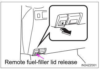
Refueling
Before refueling, close all the doors, windows, and the liftgate/trunk lid, and switch the ignition OFF.
To open the fuel-filler lid, pull the remote fuel-filler lid release.